Generally, electronic products have a step-down transformer that enables the DC power supply to convert AC mains voltages to a DC voltage (often small). The process involves converting a higher AC to lower AC, then to a low voltage DC, using a switch-mode transformer. While the process is sufficient in the long run, it can be expensive and bulky since it will also require a larger space during the design and manufacture of the product. Therefore, a cheaper and better alternative that you should look into is the transformerless power supply. Besides being a switch-mode power supply, it is less costly and small in size. Additionally, you can use it in a wide range of electronic components such as household appliances.
Contents
What is a Transformerless Power Supply?
As the name suggests, a transformerless power supply circuit uses no inductor or transformer when providing a low DC from the mains’ high voltage Alternating Current. It works by making a high voltage capacitor drop the AC primary current (120V or 230V) to a low current level (12V, 5V, or 3V).
The lower level is suitable because it ensures optimum functioning for the connected load or electronic circuit. Thus, you should get the transformerless power supply for the circuitry when using an electric circuit that requires low currents (like a few milliamperes) or in microprocessor circuits.
The transformerless circuit has a working principle that involves inrush limiting, supply voltage division, regulation, and rectification – to be discussed in the power supply structure.
Transformerless Power Supply Advantages and Disadvantages
As with any other technological equipment, the transformerless power supply has its advantages and disadvantages.
Advantages
- First, it is cheap.
- Then, it requires less space hence making it less bulky, as opposed to a transformer-based application which is chaotic and weighty.
- Also, you can use it in low-powered electronic components.
Disadvantages
- First, excess heat dissipations by the resistive transformerless power supply lower the final output voltage hence reducing its efficiency.
- Unfortunately, the maximum current output you can get is approximately 1 ampere. It is not favorable for current inductive or resistive loads that require 20 A or 30 A to operate.
- Again, the circuit has no isolation from the input supply hence making it risky to handle (no isolation between the exit and the entry). Moreover, a slight breakage or detachment of a component from the circuitry will destroy the whole device.
- Lastly, the setup and low output are not fit for more complex systems such as in safety or medical devices.
Luckily, the transformerless power circuit design we described has various stabilizing stages after the bridge rectifier. In this way, the risks become low.
Transformerless Power Supply Circuit Diagram Introduction
https://en.wikipedia.org/wiki/Capacitive_power_supply#/media/File:Capacitive_Power_Supply.png
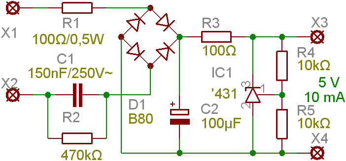
(a circuit diagram of a transformerless power supply)
The circuit diagram is shown above of a transformerless power supply circuit functions by converting high AC voltage to low DC voltage without an inductor or transformer. In the next section, we are going to break down how the circuitry works.

Transformerless Power Supply Structure/ Design
A few precautionary measures you should take before making the transformerless power supply circuit include;
- First and foremost, working with the AC input voltage without quality knowledge and experience is extremely dangerous. Therefore, handle the circuit with extreme caution.
- Second, use a Zener diode or a resistor with only a 1 Watt or above (5w) rating.
- Thirdly, if you lack a Zener diode, you can use an IC voltage regulator to regulate the voltage.
- Also, do not attempt to replace the X-rated capacitor with another capacitor. The reason being the other capacitor will burst.
- Further on, for safety reasons, you can use a 1 Amp fuse before the X-rated capacitor and in series with the phase line.
- Space the components sufficiently.
- Moreover, avoid touching any points of the dropping capacitor even if you have switched the circuit off to prevent being shocked.
- Last but not least, use a different value of X-rated capacitor should the product require more output current and output voltage.
Components
The components of a transformerless power circuit include;
- R1: 1-Ω resistor, 5W.
- R2: 10-Ω resistor; the load here should not be less than 10 Ω.
- R3: 470-kΩ resistor, 1W.
- R4: 1-Ω resistor, 5W.
- R5: 200-mA fuse.
- Voltage dropping capacitor/ X-rated capacitor (the main component) – available in 230V, 400V, 600V Alternating Current, or even higher.
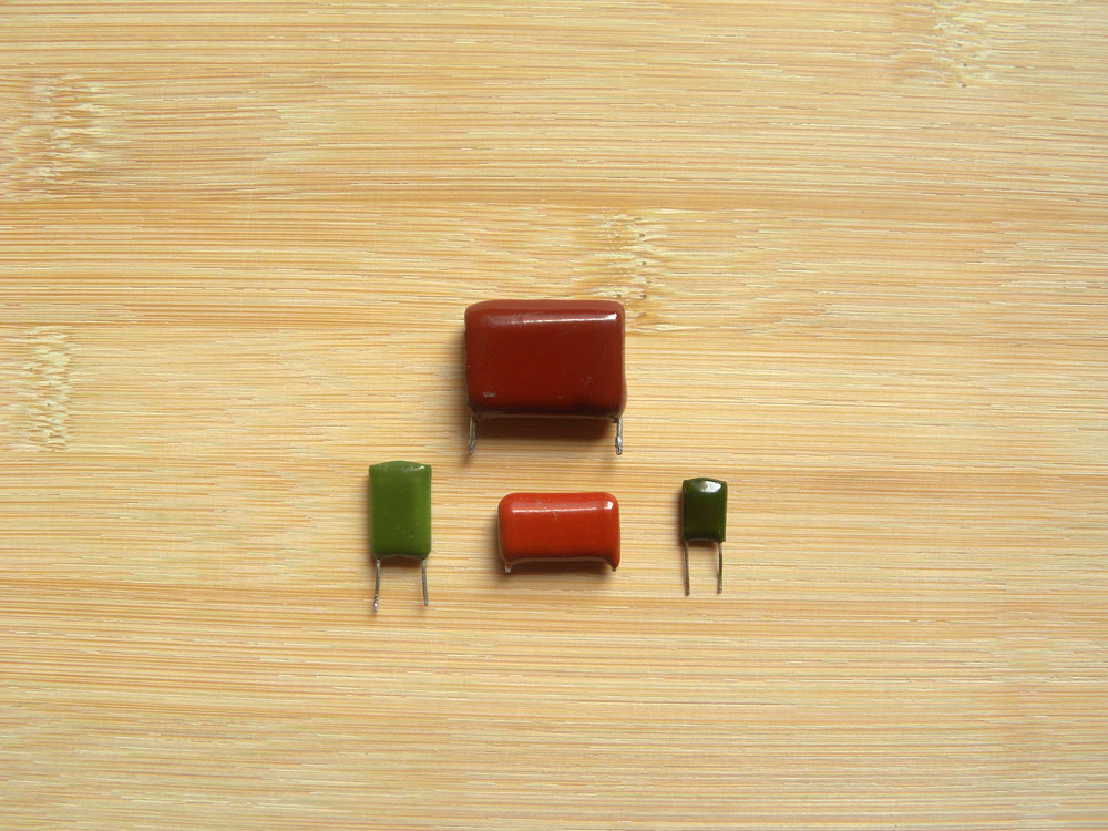
(types of capacitors).
- C1: 33,000 – µF polarized electrolytic capacitor, 25 VL.
- C2 and C3: Non-polarised capacitor made of polyester ≥ 400 V, 10 µF.
- D1: Diode 1N4007.
- D2: 12-V, 3-W Zener diode.
- D3 to D13: 1N4007.
The ideal transformerless design
- Capacitor C1 reduces the high current from 120V or 220V mains to a suitably lower output DC load. Thus, one microfarad from C1 produces about 50mA current to the output load.
- R1 resistor provides a discharge path for C1’s high voltage when you unplug the circuit from the mains input. It is because C1 can store the high volts i.e., 120V or 220V, and cause a high voltage shock when you touch the plug pins in its detachment state. R1 will discharge the high voltage quickly.
- D1 to D4 diodes function as a bridge rectifier that converts low current AC from C1 into low current DC. C1 does not restrict the voltage to 50mA but restricts the current. In other words, the DC at the bridge rectifier’s output is the peak value of 220V. The calculation is as follows;
220 x 1.41 = 310V DC. We will end up with an approximately 310 V, with 50 mA at the bridge’s output.
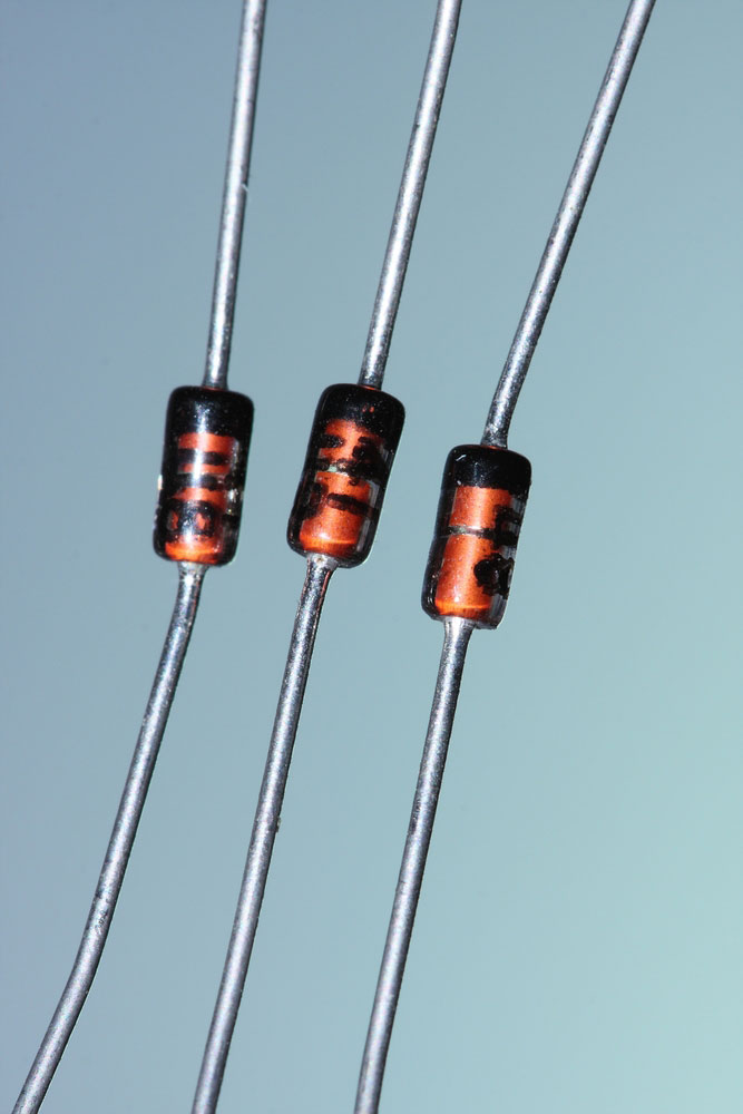
- 310V is, however, too high for a low voltage except when using it in a relay. Thus, you will use the correct Zener diode rating to shunt the 310V DC into a desirable low level, e.g., 24V, 12V, among others.

(types of Zener diodes)
- The R2 resistor is the current limiting resistor. Despite C1 acting as the current limiter, when you instantly apply the input AC to the circuit, C1 functions as a short circuit in a matter of milliseconds. In the few milliseconds when the switch is on, a high AC voltage input of 220V enters the power circuit. Unfortunately, the high voltage levels can destroy the DC output load.
A better way to cope with the situation is by introducing NTC. But in this case, we use an R2 as the limiter.
The filter capacitor is C2. Majorly, it works by smoothening the 100Hz ripples from the bridge that you initially rectified to a cleaner DC.
Type of Transformerless Power Supply
The transformerless power supply is available in two main types, and we will discuss them in detail.
The examples are;
- Resistive transformerless power supply
With the resistive power supply, you use the resistor across the voltage dropping resistor to reduce the heat in energy form. Due to the heat reduction, there is a resistance that limits the excess current. Generally, the voltage dropping resistor dispels the heat power.
A point to note – mostly, you will find some applications using the resistor with double rated power. It is because it dissipates more energy across it when compared to the other types of transformerless power supply.
- Capacitive Transformerless Power Supply
The second type, capacitive power supply, operates on low power loss, and heat dissipates, making it more efficient.
Structure; Here, the X-rated capacitor has a connection of 230V, 400V, and 600V in series. Then, the mains act as dropping capacitors and function to drop the voltage.
Difference between the resistive and capacitive transformerless power supply
Mainly, the two types differ. There is less to zero energy loss and heat dissipation in the capacitive power supply circuit as the voltage dropping resistor drops the excess voltage. On the contrary, a resistive type will dissipate extra energy as heat across the voltage dropping resistor.
Transformerless Power Supplys 12v
We will use the diagram above to discuss this third type, the transformerless power supply 12V.
Principle of action; it uses a Zener diode, bridge rectifier, capacitor, and resistor to convert a 220V mains AC voltage to a 12 DC voltage.
- C1 acts as an X-rated capacitor that will drop the elevated AC voltage.
- D1, D2, D3, and D4, which are the bridge rectifier diodes, convert the alternating current (AC) to direct current (DC) through rectification. Rectification results in conversion of 230V AC to high 310V DC because of the Peak RMS in AC signal.
- Thirdly, the C2 capacitor gets rid of the ripples that the DC voltage has obtained.
- Then, the R1 resistor eradicates the stored current that comes about when you switch off the circuit. On the other end, the R2 resistor, used for inrush current limiting, limits the excess current flow.
- Further, the Zener diode removes the peak inverse voltage then proceeds to stabilize and regulate the output DC voltage to the required 12V.
- To ensure if it is working or not, you connect the LED to the circuit.
- Finally, you enclose the circuit wholly with a shockproof material to prevent damages and electric shocks. In addition, you can connect a small isolation transformer at the power supply’s input to isolate it from the main AC supply.
- Transformerless Power Supply Application
Often, the transformerless power supply has a range of applications in low-cost and low power electronic components such as;
- Analog to digital converters,
- Systems in telecommunication,
- Digital communication systems,
- Circuitry in regulator and voltage divider circuits,
- Electronic toys,
- Mobile chargers,
- LED bulbs, and
(white LED strips for voltage 12V and 24V with adjustable)
- Emergency lights.
Conclusion
In summary, a transformerless power supply circuit is a solid replacement for a transformer-based power supply. It is in terms of bulkiness, cost, and size. Despite producing low currents, the transformerless circuit has benefitted electrical appliances with lower voltage needs.
Since it has specifications in the procedure, it is best to take extra precautions during your DIY moment. A read of this article will enlighten you and highlight the necessary steps. If, however, you have pending questions or thoughts, feel free to contact us. A solution to your need is a solution to the technological world.


