Contents
What is a Transistor Latch?
A latch is a circuit that becomes fixed in a particular state. In other words, it locks its output when it receives a temporary input trigger signal and remains in that state—even when you take out the input signal.
Here’s the best part.
The latch circuit will remain in this state indefinitely until it receives an external signal or you reset the power.
Latch circuits are similar to silicon-controlled rectifiers (SCR). Plus, they are useful in alarm circuits where a small trigger will be put on the alarm.
Additionally, the latch is a kind of logic circuit also known as a bistable-multivibrator. Why? Because it has two stable states known as active low and active high. Plus, what determines the state of the circuit is if the operation starts with a high or low input signal.
Also, it has two inputs and one output. The first of the two inputs is the SET input, while the other is the RESET input. Latches are like transistors with three terminals that function as a base, collector, and emitter.
What sets the two apart is that once the base terminal receives enough current in a latch, the current will permanently flow from the collector to the emitter.
On the other hand, current will only flow across the collector to the emitter when the base receives enough current in a transistor.
So, what is a transistor latch? Simply put, a transistor latch uses two or more transistors to form a latch circuit. So, if you don’t have any available SCR, you can build a DIY latch with transistors.
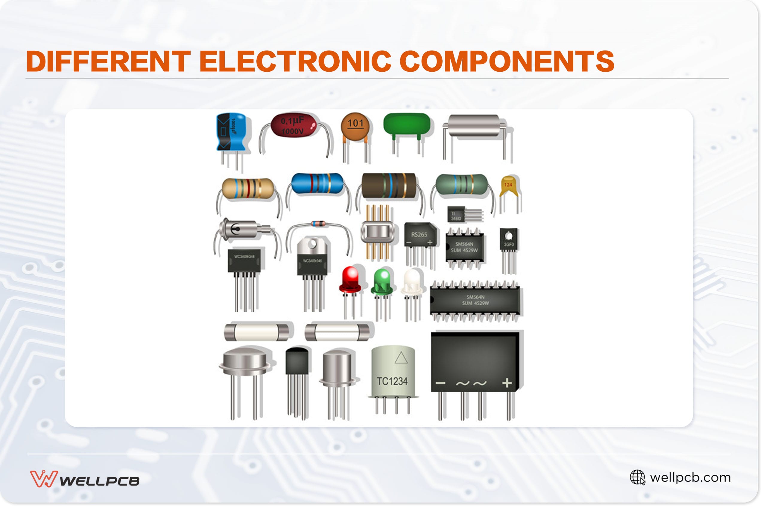
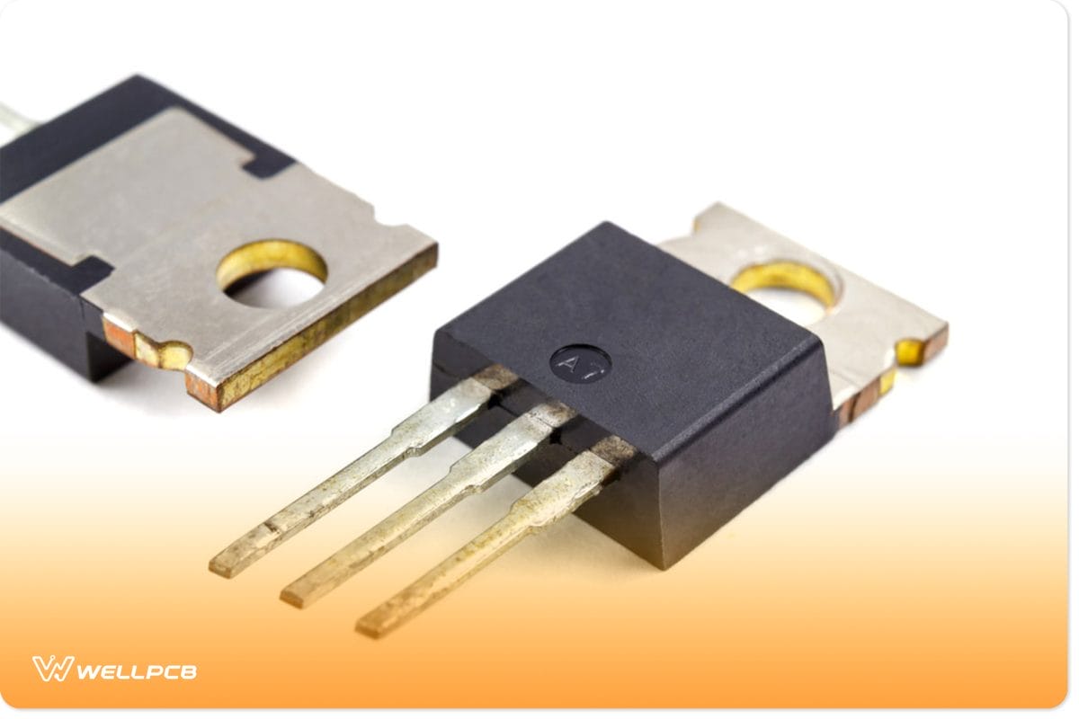
Transistors
How Does a Latch Work?
As mentioned earlier, latch circuits can work in two stable states depending on the signal used to trigger operations: high or low.
For active high-latch circuits, both inputs are normally low. Plus, a momentary high signal triggers the circuit on any of the inputs.
For active low-latch circuits, both inputs are normally high. Plus, a momentary low signal triggers the circuit on any of the inputs.
So, here’s the circuit we’ll use to explain how a latch works:
Before we go into the explanation, it’s important to note that transistor Q1 BC557 is an NPN transistor, which turns on when you apply a small positive voltage to its base. Also, transistor Q2 BC557 is a PNP transistor that turns on when applying a ground or negative voltage to its base.
A set of PNP Transistors
What Are the Necessary Steps to Take When Building a Transistor Latch
In the beginning, both transistors are in an OFF state with relays deactivated. The base of the PNP transistor BC557 stays connected to positive voltage with a current limiting resistor (R3) –to avoid accidental conductions. Plus, the circuit also uses a capacitor (C1) to prevent any false triggering of the circuit.
Now, when you apply a small positive voltage to the transistor BC547’s base, it turns on the transistor and connects the base of Q2 to the ground. The resistors (R2 and R3) stop short circuits from happening in this condition. So, when you ground the base of transistor BC557, it begins energizing and conducting the relay coil. This turns on the relay and activates any device connected to the relay.
Everything seems like normal behavior, but what makes it a latch circuit is the connection of Q1 to the base of Q2 through a current-limiting resistor (R4). So, when Q1 turns on, the current will flow in two directions.
First to the relay and the other to the base of Q1. Thus, the feedback voltage to the base of Q2 keeps the transistor Q2 on for an indefinite period after terminating the input trigger voltage. Thus, this keeps the second transistor on indefinitely and forms a latch.
Hence, any alarm or device connected to the relay will stay on until you break the latch state or reset the power.
However, if you don’t want to add any appliances to your transistor latch or just want a buzzer or an LED, all you have to do is remove the relay and connect the buzzer or LED in place of the relay with a resistor.
How to Make a Transistor Latch Circuit
Now, we will show you how to use two transistors to form a latch. First, let’s take a look at the circuit diagram and components before we dive into how to build one:
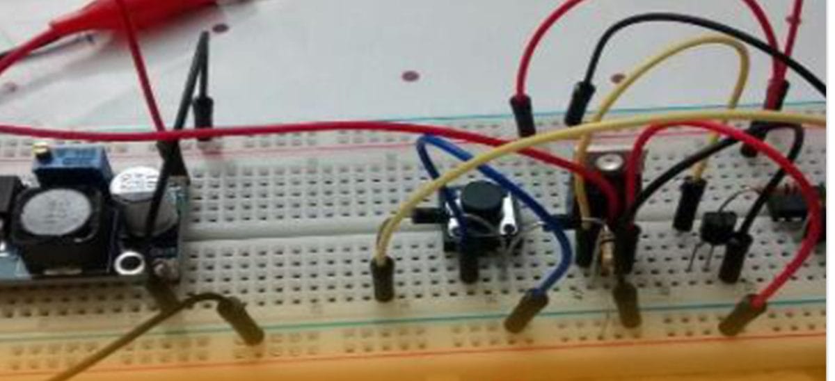
Also, here is the assembled breadboard circuit of the above circuit diagram:
Circuit Components
- LED
- (2) 2.2KΩ resistors
- 1KΩ resistor
- 330Ω resistor
- Power source
- BC547 NPN transistor
- BC557 PNP transistor
- Breadboard
Building the Circuit
For this circuit, your first transistor is the BC547, while the second transistor is the BC557.
The first step is to install one 2.2kΩ resistor into the transistor base of the BC547. It helps to limit the current that flows into the BC547. Resistors are important for the bases of BJT transistors. Otherwise, you’d fry your transistors.
Next, install the second 2.2kΩ resistor at the top of the circuit to limit the current flowing into the base of the BC557 transistor.
Also, install the 1kΩ resistor according to the breadboard circuit diagram. This resistor helps you limit the current flowing into the base of transistor 1 from the output of transistor 2.
Finally, install the LED, 330Ω resistor, and power source according to the breadboard circuit diagram above.
Once everything is in place, there are two possible currents that the base of the BC547 transistor can receive. On the one hand, there is the current the input voltage source produces, VIN. On the other hand, there’s the current that flows into BC547 from the bc557.
Now, the current from the input voltage source is important for triggering the latch circuit. While the other currency from the output of the BC557 is necessary for keeping the circuit latched on.
Lastly, the LED and the 330Ω resistor serve as the output of the circuit. Also, a 330Ω resistor helps limit the current to the LED to prevent damage.

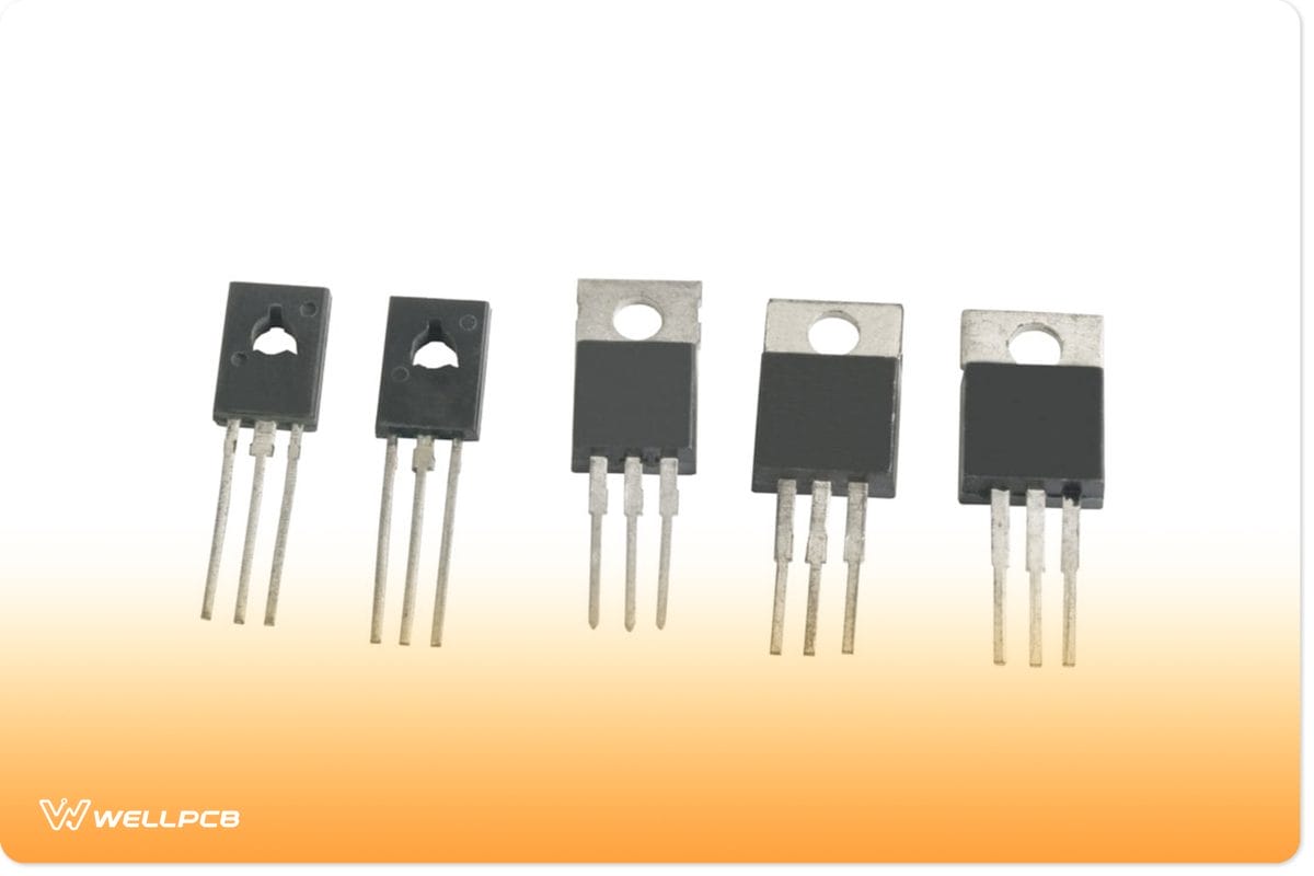
LEDs
Rounding Up
Latches are the smallest units of memory. You’ll find them in most circuits and shift registers because they apply the input(s) to their output as long as you enable them. There are a few basic types of latches, and each of them is useful in certain applications.
Also, latches belong to a group called memory elements, with their counterparts being the flip-flops. Though the two are quite different, they have similar uses in different applications.
Well, that rounds up everything you need to know about transistor latches and how to make them. If you need more information, feel free to reach us. We’ll be happy to help.