Contents
What is DAC (Digital to Analog Converter)?
DAC (Digital to Analog Converter) is an IC that converts digital values, in the form of digital codes, to analog voltage/current. Often, computers use DAC to understand its analog operation by other digital devices like cell phones.
(multiple digital to analog converters)
How Does a DAC Work?
We’re going to a concept of using a microphone to record audio through a computer.
Under such a circumstance, the audio signal/speech is a physical variable that needs digital formatting before recording on the computer. Therefore, we’ll use Analog to Digital converters.

(microphone).
Later, if you wish to play the recorded audio through a speaker, you’ll employ a DAC. It’ll convert the digital signal to an analog signal.
Types of DAC
Binary Weighted Resistor D/A Converter Circuit
You’ll need a current source or resistor to convert each digital input bit in this DAC. The resistors have a connection across the summing point and inputs. And through a summing amplifier circuit, you’ll generate the output.
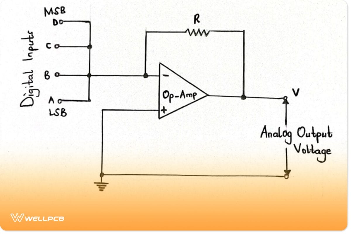
Circuit diagram of a binary-weighted DAC
From the diagram above, we can note the following;
- First, existing components include an operational amplifier, a feedback resistor, and four other resistors connected at the op-amp’s input terminal.
- The resistors at the op-amp’s terminal are variable resistors.
We will use the equation below to get the output voltage of the summing amplifier circuit.
Vo = –R (DR+ C2R +B4R+ A8R)
Therefore;
The letters D, C, B, and A are digital inputs with different values. A is at the LSB, whereas D is at the MSB.
V = Output analog voltage
Binary ladder or R–2R ladder D/A Converter Circuit
A binary ladder DAC has two resistor values, 2R and R. However, its conversion speed often reduces because of parasitic capacitance.
Further on, the input bit controls the switch between the inverting input and the ground of the op-amp. After the binary information gets into the resistors (2R), you’ll obtain the output at the bottom of the binary ladder.
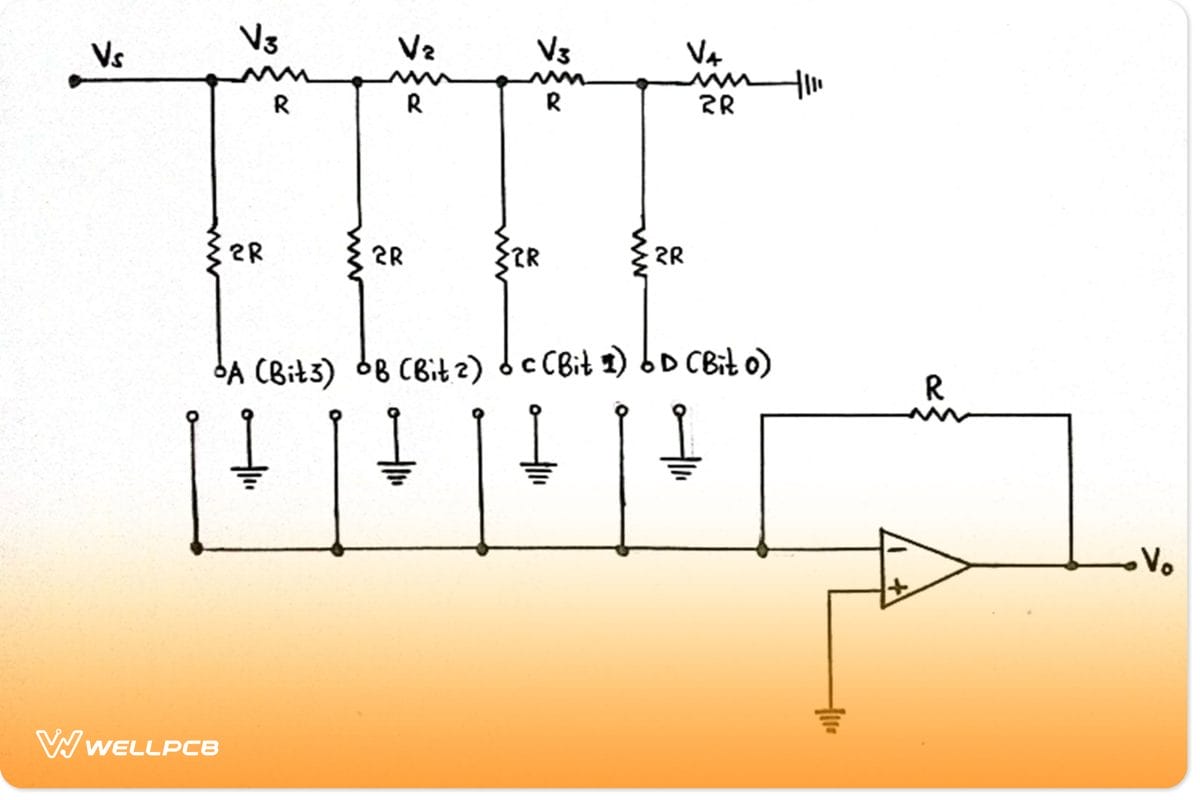
Circuit diagram of an R-2R Ladder DAC
The formula for getting the output voltage of the binary ladder is as follows;
Vo = –R × (D2R+ C4R +B8R+ A16R)
Segmented DAC
Segmented DAC is a type of DAC whose design bases its specifications on performance. It’s a combination of two or more DACs since it requires no architecture. For instance, you’ll combine thermometer-coded DAC with Binary weighted DAC, then separate the input binary code into two segments.
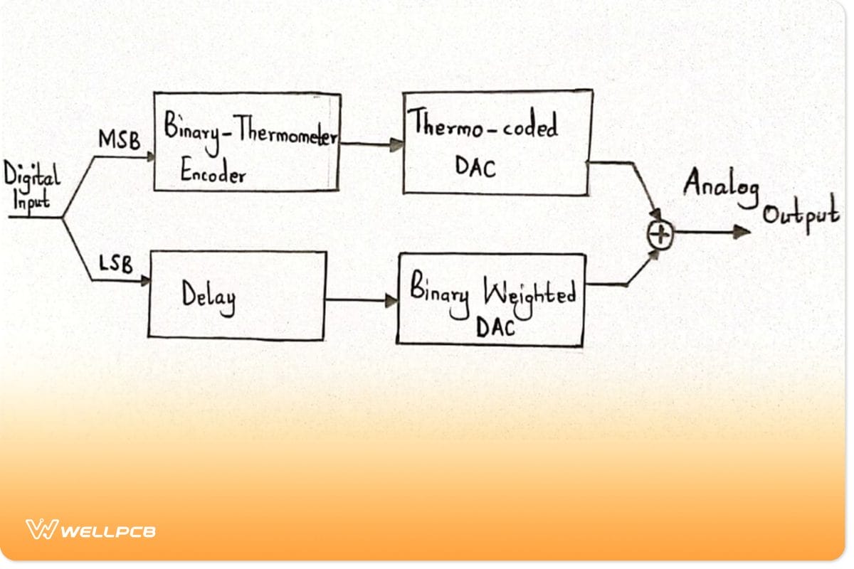
A segmented digital-to-analog converter
The binary-weighted structure will work in LSB, while thermometer-coded DAC applies in MSB. In that way, you’ll have a compact chip.
In addition, as the input bits increase, the encoder size grows. Therefore, you’ll need more interconnections and switches.
Delta-Sigma DAC
A delta-sigma DAC is by far the most precise and fastest. It also comprises different blocks, as listed below;
- Interpolation filter. It reduces the sampling time while increasing the sample rate, increasing the sampling frequency by four times. The filter data then gets to the modulator block as input.
- Delta–sigma modulator. The modulator functions as a low-pass filter to the input signal and a high-pass filter to the quantization noise.
- 1–Bit DAC. Each bit is converted from digital samples to analog forms for added amplification.
- Analog output filter. Here, the block filters out the DAC output and then produces the analog signals.
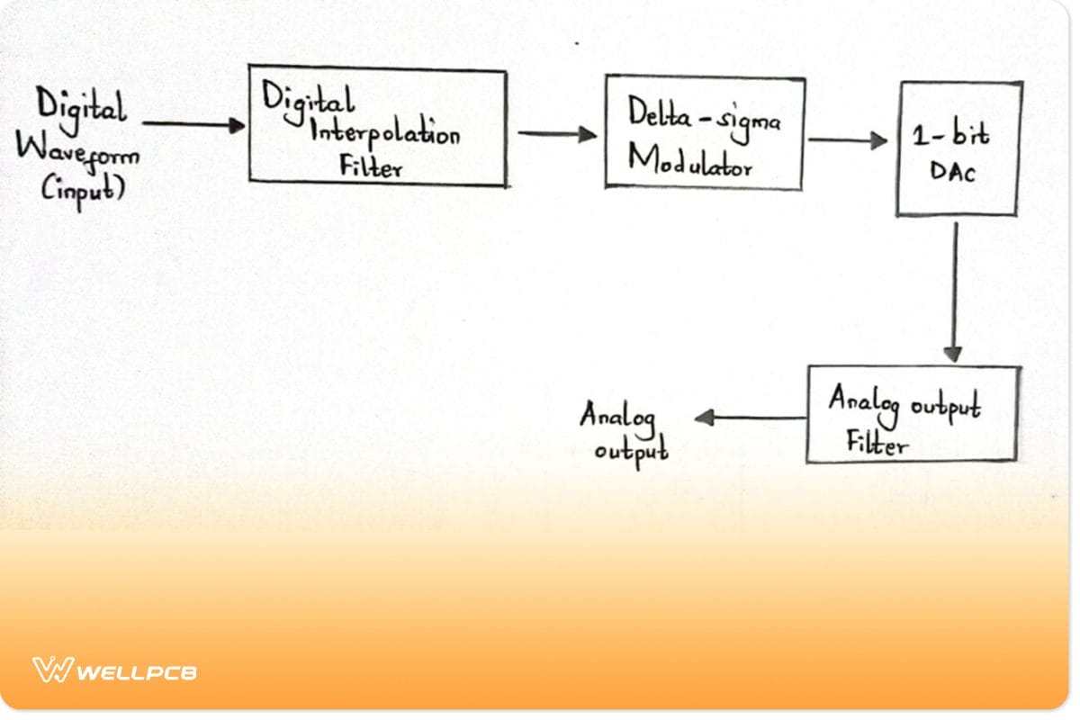
Delta-sigma DAC
Advantages and Disadvantages of DAC
Advantages
- First, you can achieve high accuracy and resolution with it.
- Then, you can implement it easily.
- Lastly, one of the DAC types, i.e., weighted resistor circuit, is a fast-converting circuit compared to other converting methods.
Disadvantages
- The binary-weighted resistors emit a high-power dissipation.
- Secondly, resistors in the circuits can lead to non-linearity, offset error, and gain error.
- Some of the DAC circuit types may need a few other components, which is impractical. However, there are available discrete DAC chips that can use a microcontroller via I2C and SPI to communicate.
- Also, there’s a delay in R-2R ladder converters since the circuit requires switching depending on the inputs.
- Despite being accurate, it becomes impossible to produce continuous voltage values because the binary number determines the voltage steps.
- Finally, it would be best if you had the same voltage levels for each input in a weighted resistor DAC. That is to say, you’ll need four resistors for a 4-bit converter.
How to use a DAC?
You’ll often find DACs embedded into a microcontroller or used as separated integrated circuits, with the latter being more common. Common examples of IC DACs include DAC0808, DAC0832, and DAC7715, among others.
For this segment, we will use MCP4725 DAC IC to comprehend better how to use a DAC. And since it works in conjunction with an Arduino, it’s easy to find its libraries and documentation.
Features of MCP4725 DAC IC
- First and foremost, its packaging is available in a SOT23-6 package. The package’s compactness saves on storage space.
- It works well with the i2C communication interface. Therefore, it’ll use only two serial clocks and serial data pins. At the same time, speed can have a range between 100kHz and 3.4MHz.
- Further, you can change the i2C address pin by connecting it to GND or Vcc when using multiple devices.
- Last but not least, it’s got a 12-bit resolution which is better than Arduino’s 8-bit resolution. With a 5V supply voltage, each binary digit converts to a 1.22mV voltage, i.e., 5V/ (212).
DAC Applications
You can use DAC in the following applications;
- Digital potentiometers,
- The Digital data acquisition systems,
- Digital signal processing, like in audio editing,
- Digital power supplies for microcontrollers.
Conclusion
To conclude, DACs are undoubtedly crucial components that link analog and digital signals. For that reason, they enable a connection between machines in general by converting binary count to a discrete voltage level.
For questions or clarifications, contact us.