Contents
- 1 What is the basic working of an inverter?
- 2 Inverter Classification According to the Output Characteristic
- 3 Inverter Classification According to the Source of the Inverter.
- 4 Methods of Commutation-Wise Classification
- 5 Connections of Thyristors and Commutating Element Wise Classification
- 6 Modes of Operation Wise Classification.
- 7 Classification According to Control Technique.
- 8 According to the Number of Levels at the Output
- 9 Conclusion
What is the basic working of an inverter?
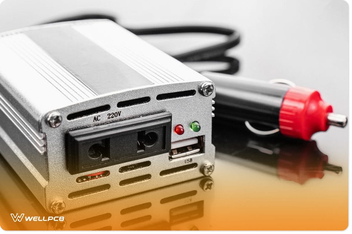
Fig 1: A Car Power Inverter System
Inverters change the direct current from fuel cells, solar energy, and batteries to AC power. Further, they assist in speed and torque control in electronic motors. You’ll come across the following top five ranges of inverters in power electronics:
High Capacity Inverters
They feature a relatively high rating. Thus, they can take heavy loads of up to 2KVA. They are common in commercial applications with high load voltage demands, such as petrol pumps and showrooms.
Connected Inverters
These allow control techniques such as WiFi technology and Bluetooth on a mobile/smartphone application during use. Among the controllable features include
- input voltage
- battery capacity level
- backup time
- inverter load
Examples of such inverters include Zelio-I and Zelio-Wifi.
Standard Inverters
These are the inverters that best suit use by household electronic devices that require minimal power.
They come in several types, such as
- Eco watt series (300 VA to 1500 VA rating)
- Pure sine wave output series (600 VA to 1500 VA)
- Shakti charge series inverters
Integrated Inverter
It combines a high voltage level battery with an inverter, thus offering more backup. Also, they have a Li-ion battery for power and last for an extensive period.
Premium Inverter
These current source inverters give real-time data on the inverter’s load and battery charging percentage. Besides, they apply the advanced 32-bit DPS processor and sine wave technology.
Inverter Classification According to the Output Characteristic

Figure 2: Solar Inverters
There are three inverter kinds under this category.
Square wave inverter
The square wave inverter’s output waveform is a square wave. However, it is one of the most underutilized types, as almost all electronic devices use the sine wave supply. All in all, it is essential in simple tools featuring a universal motor.
Sine Wave
It outputs a sine wave, which is handy for almost all electronic devices. Nonetheless, it is relatively pricier than the square wave inverter. Also, it is common in commercial and residential electronic circuits.
Modified Sine wave
The inverter output is neither of the two kinds we’ve covered above. Instead, it is a sum of two square waves with a shape closely resembling a sine wave.
Inverter Classification According to the Source of the Inverter.
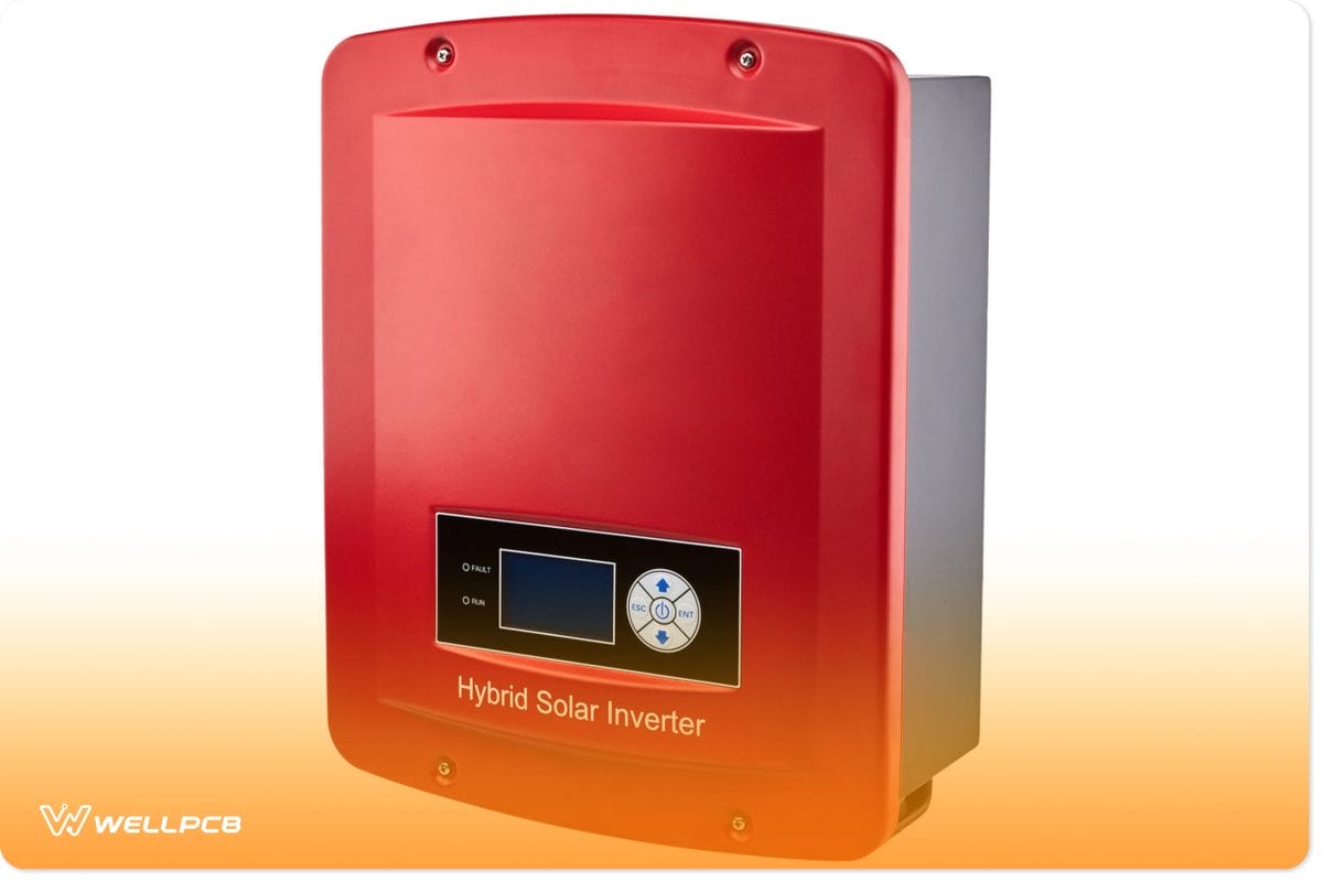
Fig 3: A hybrid solar inverter
Under this tier, there are two inverter types.
Current Source Inverter
The CSI’s input is a current source. Primarily it is essential in medium voltage industrial applications, although it’s not as popular as others in this list.
Voltage Source Inverter
Similar to the above inverter, the input acts as the voltage source. Its key characteristics include high response, efficiency, and reliability. In addition, VSIs allow motor operation without derating.
Methods of Commutation-Wise Classification
Fig 4: An Inverter Icon
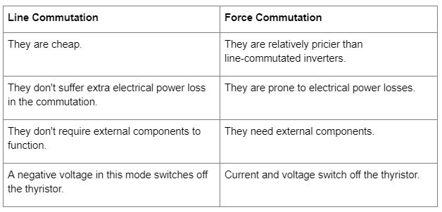
Silicon-controlled rectifiers are of two kinds based on their commutation techniques. The commonly used types include line commutated and forced committed. However, there are others, such as complementary commutated inverters and Auxiliary commutated inverters.
Line Commutated Inverters
They operate via a line commutation process. Fundamentally, they will switch on when the silicon controller rectifier senses zero characteristics.
Forced Commutated Inverters
Unlike those above, these inverters lack zero points in their commutation process. Instead, they need the action of an outside force to instigate device commutation. It is the force commutation process.
The table below highlights the key differences between the two inverters.
Connections of Thyristors and Commutating Element Wise Classification

Fig 5: A Thyristor
Series Inverters
Their circuit features a resistor, InInductorand capacitor (RLC), and two thyristors. One of the thyristors in the series inverter is in parallel configuration with the RLC circuit. Meanwhile, the other is in a series configuration in the middle of the RLC circuit and DC power source.
Hence, the name series inverter stems from the series connection of the load terminals with the DC source. Also, others refer to these inverters as self-commutated inverters or load-commutated inverters.
Mode of operation of Series Inverter
It features two thyristors that convert direct current to AC. However, one thyristor at a time is functional (turned on) during operation. Otherwise, if they were on simultaneously, they’d short-circuit. Besides, switching both thyristors on would damage the course hence the essence of a time delay on one of them.
Mode 1
Primarily, both thyristors are off. But, when thyristor 1 is on, the other thyristor switches off. Hence, switching on Thyristor 1 prompts DC power to flow from the input source to the LCR load. Also, the current flow in this mode is from the capacitor’s end to the resistor’s end.
Mode 2
Converse to mode 1; when thyristor 2 is on, thyristor 1 is off. Also, before a thyristor switches from the former mode to this one, a time delay is significant. It allows thyristor 1 to turn off. Next, after thyristor one goes off, thyristor 2 goes on, allowing current flow via the latter to the load.
Current alternation causes a shift from DC power to AC power, which is in line with the inversion mode principle. The recent direction/ power flow shifts from the resistor end to the capacitor end. Hence, by shifting the flow direction from one mode to the other, the inverter plays its inverting role.
Key Advantages
- Series configuration inverters are useful for induction heating which needs a high current.
- Also, they are useful power tools for Florence lighting and are essential in high-frequency operations.
Parallel Inverters

Fig 6: A DC to AC Car Inverter
They also feature two thyristors, an inductor, a center-tapped transformer, and a capacitor. Fundamentally, the thyristors facilitate the flow of current by providing a path. Further, the Inductor ensures the current source is constant. Also, there’s a commutation capacitor to switch T1 and T2 on and off via complementary commutation.
Under this switching technique, when you switch T1 on, T2 receives a firing angel. Next, the capacitor control switches off T1. The transformer facilitates the switching frequency shift from DC to AC power output.
Mode of operation of Parallel Inverter
The module inverters operate via two modes.
Mode 1
Triggering thyristor 1 prompts the commutated capacitor to switch off T2. Consequently, there’s a power flow in the transformer’s primary winding. Further, this stimulates the clockwise current flow in the secondary transformer winding.
Mode 2
Triggering T2 shifts the mode of operation of the commutated capacitor. In this case, it’ll switch off T1, thus shifting the power flow in the primary winding. Next, there’s a resultant anti-clockwise current flow in the secondary transformer’s winding.
Parallel Inverters Advantages
- Parallel inverters have a more stable load voltage than series configuration inverters.
- Also, it’s cheaper than series inverters as it needs only two control switches and a transformer.
- Additionally, parallel inverters function via simple class C commutation. Besides, they don’t carry all the load current.
- Lastly, the parallel inverter module requires limited control switches.
Bridge Inverter
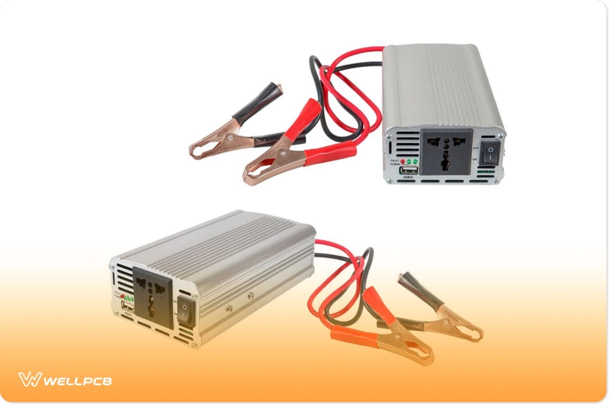
Fig 7: Power Inverters
They include single-phase H-bridge inverters and three-phase H-bridge inverters.
Half Bridge Inverter
They rely on dual electronic circuit switches, which can be either of the following components:
Notably, if the half-bridge inverter features BJT and thyristors switches, it needs two additional feedback diodes. The only exception to avoiding the freewheeling diodes is exclusively resistive loads. Conversely, MOSFETs have a single diode.
Generally, A half-bridge inverter has two complementary thyristors that go on and off in turns. Also, they function in two modes when operating resistive loads. Lastly, the thyristor switching frequency is dependent on the underlying output frequency.
Mode 1
The switches start at a closed position, and then T1 switches on as T2 goes off. The current waveform in this mode is opposite to that of Mode 2.
Mode 2
The opposite of mode 1 happens, whereby T2 goes on while T1 is off. Thus, the current through load will invert the direction. The shift in the current wave direction results in the inversion of DC to AC.
Full Bridge Inverter
A Single-phase inverter will have four control switches. Each of them controls the current direction in the circuit. Additionally, this range of inverters has four feedback diodes that function only when all thyristors are off mode. The other condition is that the load is not resistive.
Lastly, in this range of inverters, the thyristors operate in pairs. Therefore, when one team is on, the other is off.
Three-Phase Bridge Inverters
A three-phase inverter is essential in running heavy loads that require three-phase power. Fundamentally, this is in industrial applications.
The three-phase inverters feature six diodes and six control switches. Also, the degree of gate pulses is the fundamental determinant of the bridges’ operation mode. The degree of gate pulses can give either the 120-degree mode or the 180-degree mode.
180-degree Mode
Three thyristors will be in conduction mode in a while to give out corresponding single phases. Also, the conduction time in this three-phase bridge inverter will be half the time a thyristor takes in the other modes above.
120-degree Mode
Here, only two thyristors are in conduction mode with a 60-degree time delay in switching. The conduction time thus changes to support this mode of conduction.
Modes of Operation Wise Classification.
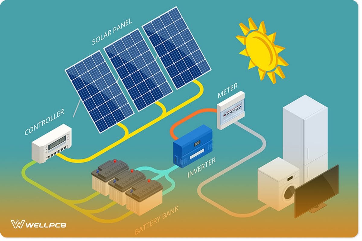
Fig 8: A schematic Illustrating power inverter operation.
There are three ranges of inverters under this class, including the following:
Stand-Alone Inverters
Also called Off-Grid mode inverters, they have direct load access without external interruption by other sources. Its independence from the utility grid is what makes it an off-grid inverter.
Further, they cannot connect to the utility bridge since they are incapable of synchronization. It is essentially matching the nominal frequency with the phase frequency.
Their upsides include
- They allow continuous power supply and deliver stable nominal voltage and frequency to the load.
- An off-grid inverter is also cheaper than the rest.
- Lastly, stand-alone inverters don’t suffer from utility grid interruptions and power failures.
Grid-Connected Inverters
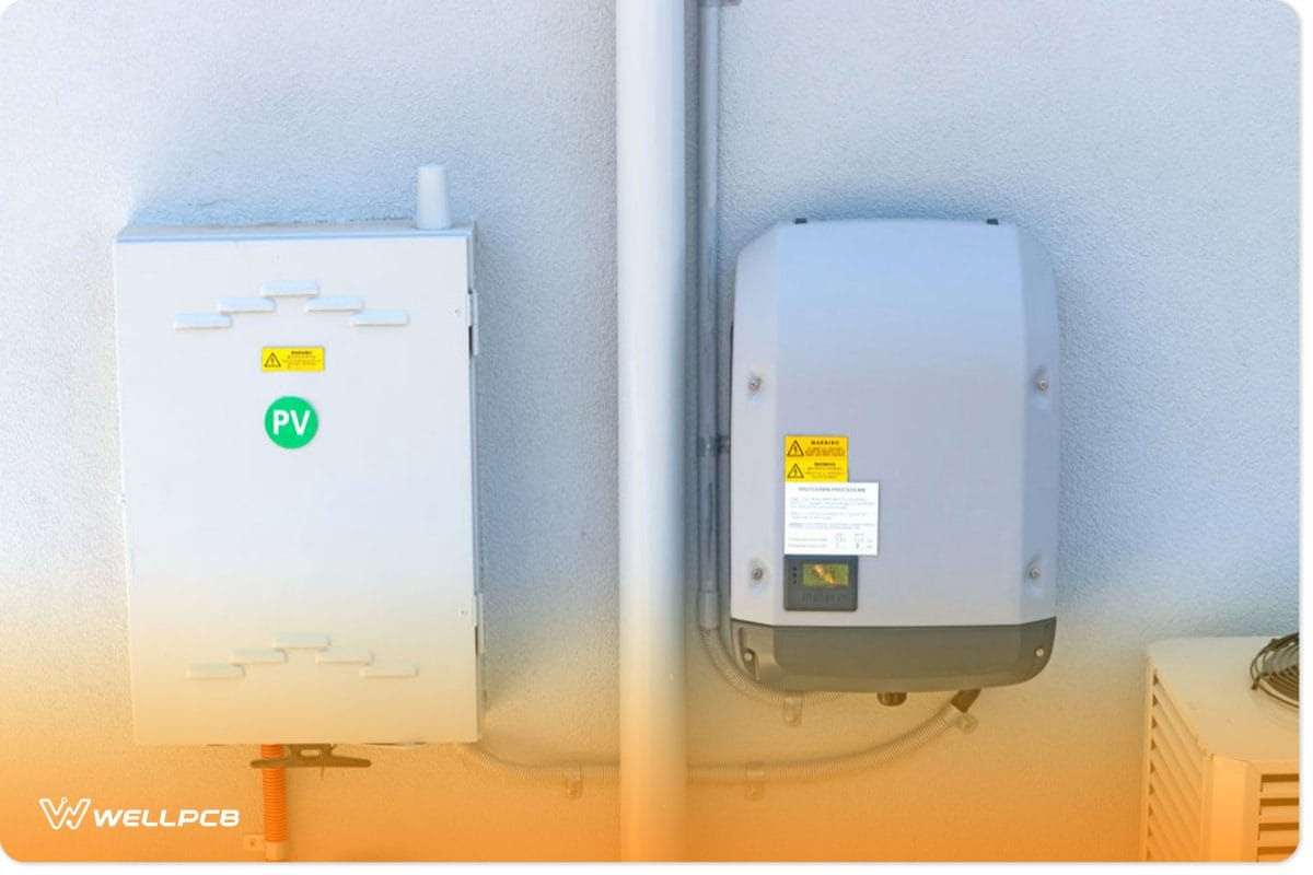
Fig 9: A Solar Inverter
A grid-tie inverter gives AC power from DC power sources. Further, a grid-tied inverter will deliver extra power to the grid.
The grid-connected inverters can synchronize the carrier frequency and the current phase. Furthermore, they increase the voltage level of DC power sources to facilitate entry into the utility grid.
Where there is maximum power transfer from a DC power source to the utility grid, the inverter produces a 90-degree current wave shift. It is in line with the power transfer theorem. Lastly, grid-connected inverters include
a) Central Inverters
Central inverters apply the traditional inverter topology and are easy to design. However, they are not easy to expand and are prone to breakdown if one part of the system breaks. Also, they are expected as solar inverters.
b) String Inverters
These solar inverters upgrade central inverters and allow scaling and easy monitoring. Nonetheless, they have a higher watt cost than central inverters.
c) Micro-inverter
Micro-inverters or module inverters enable monitoring at the module level. Further, a micro-inverter features the lowest DC wiring cost of all grid-connected inverters.
Bimodal Inverters
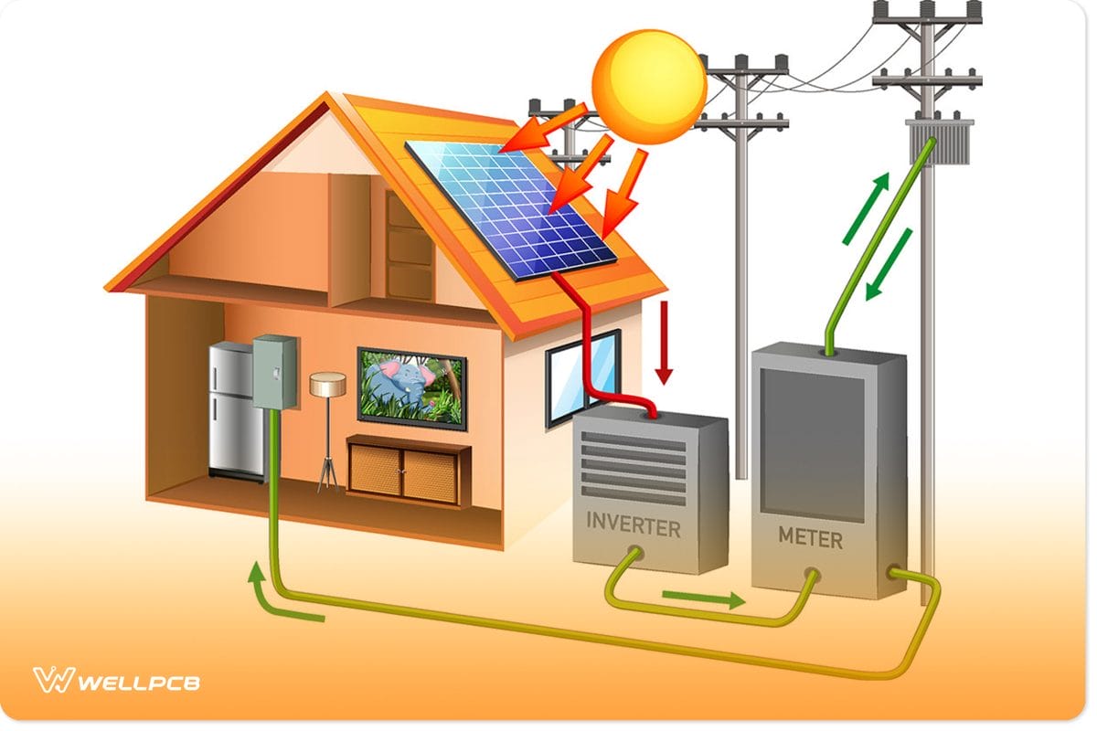
Fig 10: Illustration of a power inverter
A bimodal inverter can be a stand-alone and grid-tie inverter at the same time. Thus, it allows continuous operation of the system depending on the prevailing input signal. Bimodal inverters will go off when power from renewable energy sources is enough to drive the load.
Further, the production of additional energy by renewable energy resources prompts its mode of operation to shift to a grid tie. Then, it enables phase and frequency synchronization and feeds the power to the utility grid.
Classification According to Control Technique.

Fig 11: Industrial Inverters
There are four categories depending on PWM techniques.
Single Pulse Width modulation (single PWM)
In this mode, the reference pulse is a square wave signal with a triangular carrier wave signal. In addition, the output voltage level frequency relies on the reference signal frequency. Nonetheless, this inverter’s primary downside is its high harmonic content.
Multiple Pulse Width Modulation (MPWM)
The inverter solves the high harmonic content problem synonymous with the single PWM module.
Sinusoidal Inverter Pulse Width Modulation (SPWM)
Modified Sinusoidal Pulse Width Modulation (MSPWM)
According to the Number of Levels at the Output
There are two types under this category:
Regular two-level Inverter
They produce outputs with either a negative or positive peak voltage.
Multi-level inverter
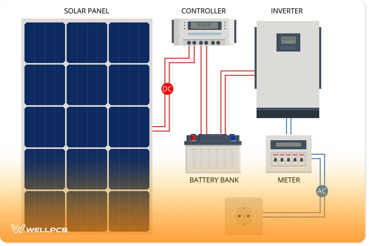
Fig 12: A Hybrid Inverter Illustration.
Their outputs have multiple voltage levels. Multi-level inverters have four subclasses that are as follows:
- Hybrid Inverter– A Solar Inverter.
- Diode-clamped Inverter
- Flying capacitor Inverter
- Cascaded H-Bridge Inverters
Conclusion
Above is an elaborate discussion of all the possible types of inverter systems. For more info, contact us.