
The UC3844 is part of a family of fixed frequency current mode controllers with exceptional performance. This series of integrated circuits offer perfect solutions. The ICs function without using a lot of external electrical components. The UC3844 design centers around a current limiting feature that works on a cycle-by-cycle basis.
In this article, we are going to discuss the UC3844 integrated circuit. We will talk about the description of each pin, connections, and, features. Also, you will learn how you can use it.
Contents
What is UC3844?
The UC3844 is a microchip with an integrated circuit that controls currently at a constant frequency. Importantly, the UC3844 comes in three types; 8 pins, 16-pin, and 20-pin. All three types of uc3844 integrated circuits work similarly.
However, we will focus on the 8-pin design. The design of this 8-pin connector is for use in off-line and DC-DC converter applications. Also, the integrated circuit has a minimal number of external components.
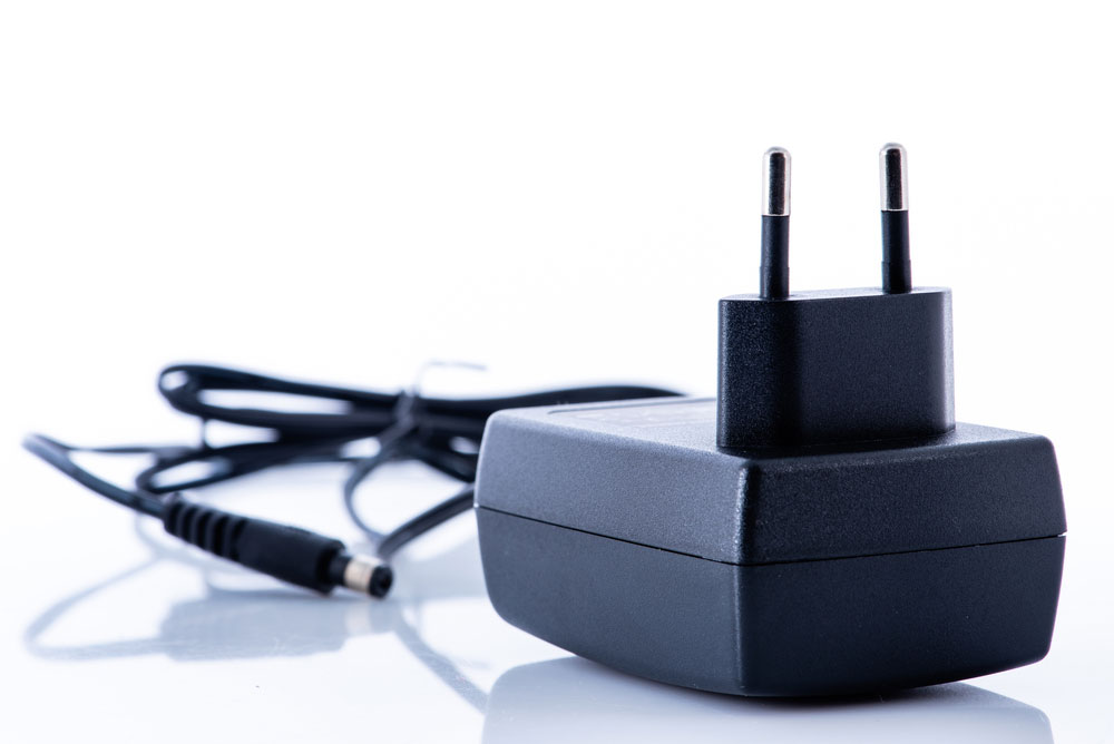
(example of an electronic device that uses a DC-DC converter application)
Pin Configuration for the UC3844


(vintage electronic resistors.)
Features of the UC3844 IC
- Firstly, the UC3844 integrated circuit is a current mode PWM controller.
- Secondly, this current mode PWM controller also offers an automatic feed-forward adjustment feature.
- Thirdly, it has a double pulse suppression.
- In addition, the current mode controller’s load response characteristics have been improved.
- The integrated circuit has an internally trimmed bandgap reference.
- This PWM motor speed controller has an under-voltage lockout with hysteresis.
- Moreover, the current limiting on this IC PWM controller is pulse by pulse.
- Also, this UC3844 motor speed controller circuit has been optimized for offline and DC-DC converters.
- Additionally, the DC motor speed controller provides a totem pole output with a high current.
- Finally, the analog design of this circuit has an output deadtime that is adjustable from 50%t.

(image of an integrated microchip.)
Specifications for the UC3844 IC
- First, the UC3844 PWM controller has an operating voltage of between 12v to 28v.
- Second, it has a switching frequency of 500kHZ
- Also, this current mode controller has a maximum duty cycle of 100% and a maximum duty clamp.
- The PWM motor speed controller also has a low start-up current of less than 1 milliampere.
- Lastly, the IC’s motor speed controller circuit has an operating supply current of 25mA

( a circuit board image.)
UC3844 Substitutes
You can substitute the UC3844 PMW CONTROLLER with the UC3843 IC or the UC3842 IC. However, some You can substitute the UC3844 PMW CONTROLLER with the UC3843 IC or the UC3842 IC. However, some alternative options are available like the UC2842 IC and the SG2524.

Where to Use the UC3844 PWM CONTROLLER
The UC3844 can deliver a steady current because it is a current-mode controller. It successfully achieves this functionality by altering the output voltage that reaches the load on a regular basis. Also, we include a current sensing comparator in the motor speed controller circuit.
Moreover, it is able to drive power Mosfet since it has a high current totem pole output. In addition, the trimmed oscillator efficiently works by controlling the duty cycle. We can use the integrated circuit PMW controller to regulate current. Otherwise, you can use it to limit the current in certain applications.

(technician working on electronic equipment.)
How to Use the UC3844 Current Mode Controller
For the connection, the input voltage of between 12v to 28v should be directed to the Vcc pin. Whereas the output pin links to the gate driver circuit. This gate driver circuit belongs to the power switch that needs action. You should know that you only require minimum requirements to control these custom devices.
On the other hand, pin 2 behaves as feedback depending on the signal the PWM controls. However, a shunt resistor works by monitoring the change in current from the circuit. Once it notices a change, you should feed the differences in the voltages to the feedback pin.
Importantly, you should place the VREF pin close to a ceramic capacitor. You do this connection so that you can enhance reference stability. Also note that, via the timing resistor, the VREF pin can give a charging current to the oscillator timing capacitor.

(image of a microchip)
Block Diagram
A representation of UC3844 block diagram

( Block diagram of UC3844 integrated circuit)
A representation of the Internal Block Diagram of a UC3844
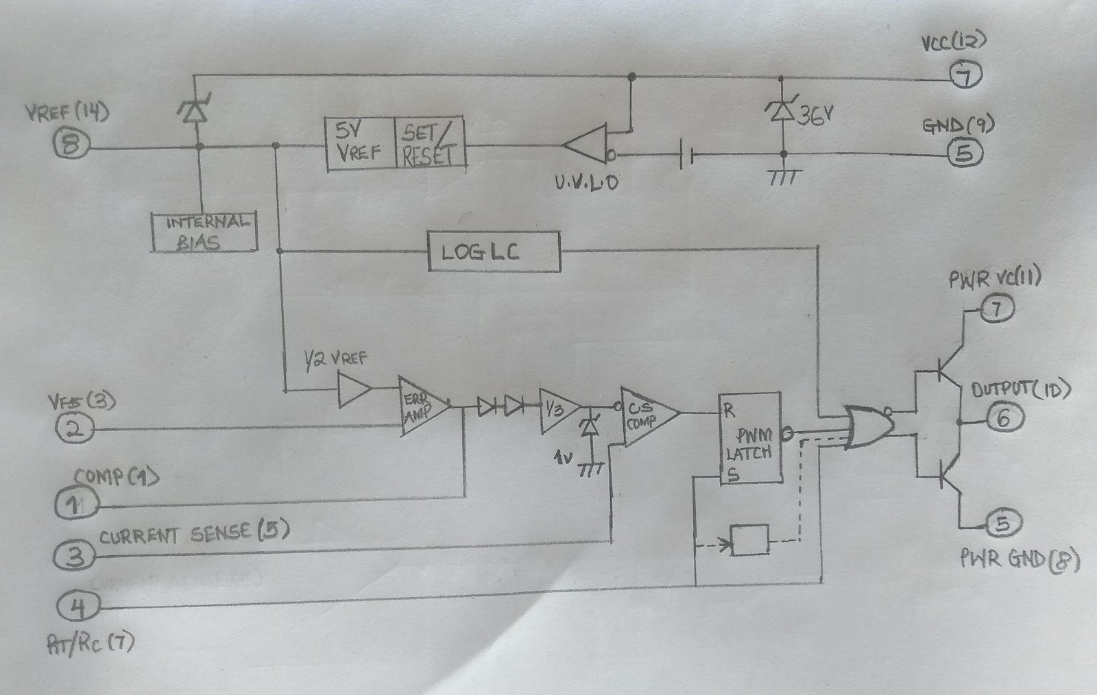
(The Internal Block Diagram of a UC3844 integrated circuit)
Applications
- Firstly, we can use these monolithic chips in a battery drain circuit.
- Secondly, due to its device packaging, we can use this series of chips in DC-DC converter circuits.
- Thirdly, this high-performance fixed-frequency current-mode controller is necessary for the electronics power supply.
- Also, we can have this device that can switch mode power supply between circuits.
- Lastly, load machines require the presence of this device in their circuits.
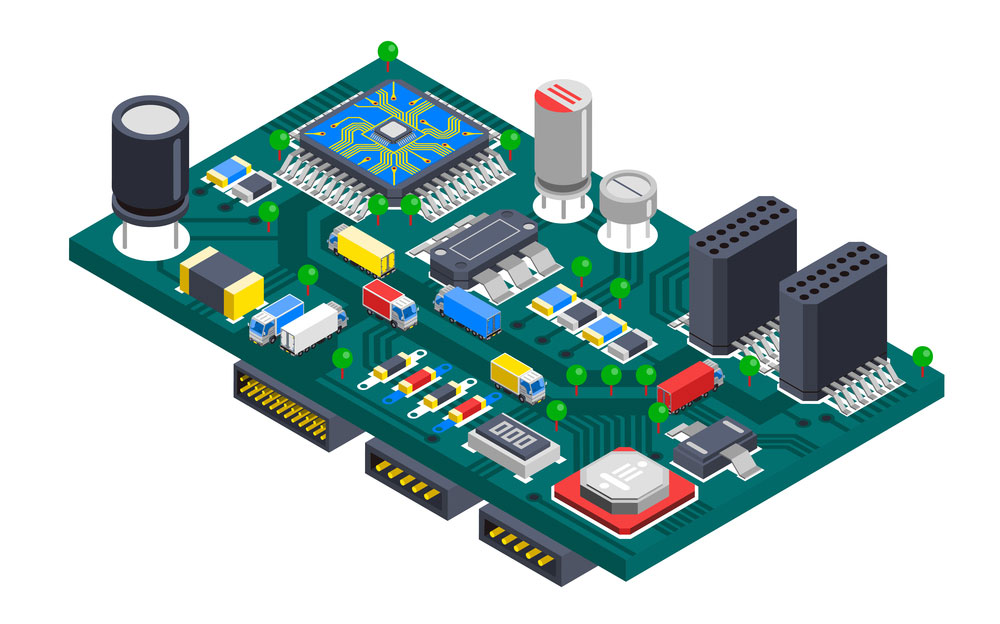
(an isometric concept of a circuit board.)
Summary
The UC3844 is a monolithic chip that helps out a lot with current control. Depending on the amount of current flowing through the circuit, this integrated circuit produces PWM signals that control a power switch.
contact us if you want more information on these topics or help make your circuit board,