Contents
USB Pinout Overview
To understand the USB pinout in its full context, you’ll need to briefly cover its history. Before the introduction of the USB standard in the early 90s, computer peripherals and devices had different cables. This made the configuration of these devices unnecessarily complicated.
Moreover, these cables had limited capabilities and they were not interchangeable. They all featured disparate dedicated ports, interfaces, and connection standards.
A conglomerate of major players in the computing industry (IBM, Intel, Microsoft, etc.) came together to create a connection interface that was:
- Universal
- Fast
- Multifunctional
This partnership birthed the USB 1.0 in 1995. It was multifunctional, simple, featured plug-and-play, hot-swappable, had fast data transfer rates, and was supported by most new computers.
Identifying The Pinouts
If you look closely at the interior of your male USB connector (especially Type A), you’ll likely discover that it has four embedded or flat pins:
The term “USB pinout” specifically refers to the arrangement of these pins. This arrangement dictates how the USB connector functions – how it exchanges data and delivers power.
You can identify each USB type by both its shape and its pin layout. In most configurations, two of the pins supply power, while the other two are for differential data signal pairs.
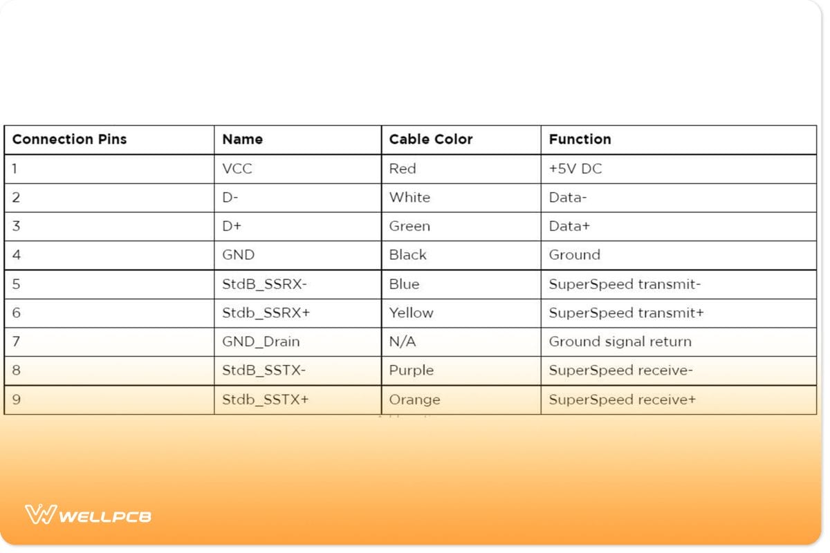
Each pin connects to a differently colored wire. The color of the cable denotes the purpose. For instance, a typical USB Type-A connector’s pin layout is as follows:
| Pin | Name | Cable Color | Description |
| 1 | VCC | Red | +5 VDC power supply pin |
| 2 | D- | White | Data- pin |
| 3 | D+ | Green | USB data cable Data+ |
| 4 | GND digital ground | Black | Ground pin |
In a standard USB 1.0 pinout, D+/DP and D-/DN usually act as differential data pairs. In essence, this means that they allow simultaneous upstream (D+) and downstream (D-) data packets between the USB host and the connecting (to) device. In addition to concurrent data exchanges, the USB pinout facilitates the simultaneous delivery of five volts of power.
Understanding USB pinout configurations is essential for troubleshooting. For instance, if your cable isn’t feeding power to your device as it should, there is likely an issue with the power pins or wires (Red and Black).
How Does a USB Pinout Work?
The architecture of the USB system consists of three key parts:
- The Host (PC, gaming console, smart TV, etc)
- The USB (to) Device (phone, external hard drive, flash drive, etc. )
- The USB Cable
The relationship between the host and the device is known as a Master-Slave connection. The host has two core responsibilities:
- Hardware: Detecting USB connections, providing electrical power, and controlling data transfer
- Software: Handling connectivity, configuring the USB devices, running the devices’ driver, and managing power or bandwidth
Ultimately, how the USB (to) device functions will depend on what host device you connect it to. Since computers are the most common host devices, we’ll use that as an example.
Connection Setup
USB devices use pull-up resistors to announce their presence to hosts and indicate their transmission speeds. For instance, a full-speed USB device announces itself by connecting a pull-up resistor to the D+/DP terminal, pulling it high to 3.3V. Conversely, low-speed devices connect to the D-/DN terminal.
So, when you plug an external device into your PC for the first time, the host device scans it and assigns it an address. Your computer will also load the necessary device driver. To do this, the host uses a product ID/vendor ID (PID/VID)—which the connected hardware or device supplies. Once the host completes the loading of necessary device drivers, the hardware/device will be ready for use.
Just like connectors, (PC) USB host controllers have dedicated specifications too. The most recognizable are as follows:
- The Universal Host Controller Interface (UHCI): Designed by Intel to support USB 1.0 and 1.1 connections.
- Open Host Controller Interface (OHCI): A standard published by Compaq, Microsoft, and National Semiconductor to define interfaces between USB and Firewire drivers. It exclusively supports USB 1.1.
- Enhanced Host Controller Interface (EHCI): Designed to handle USB 2.0 devices. Because it only supports high-speed USB 2.0, it has to rely on a companion controller to handle USB 1.x connections.
- Extensible Host Controller Interface (xHCI): A truly universal controller interface that accommodates all USB versions. This includes USB 3, 3.1, USB4, and any other other future USB versions.
There are rules and methods to ensure hosts communicate with USB devices as efficiently as possible. These are known as USB communication protocols. The Host controller uses them to coordinate data transfers between the host and the USB device.
USB Classifications and Speeds
Each of the host controllers we covered was introduced alongside a USB standard. Each USB standard supports a specific data speed (or range). The version/speed of the USB connection and device will ultimately affect the communication protocol’s behavior:
- USB 1.1 – Low-Speed (1,5 Mbps): Features simple signaling and minimal data checks for devices such as mice and keyboards.
- USB 1.1 – Full Speed (12 Mbps): Features superior error checking and more complex signaling than low-speed. It supports devices like printers and older storage devices.
- USB 2.0 – High-Speed (480 Mbps): Introduced support for new storage devices (flash drives and external hard drives) and webcams. It also offered more comprehensive error checking, packet framing, and synchronization. Isochronous transfers allowed for the prioritizing of timing over error checking. This delivered fast, continuous streams for video and audio.
- USB 3.x (And beyond) – SuperSpeed (5 Gbps): Its 8b/10b data encoding method ensures greater data signal integrity. Additionally, its introduction of full-duplex communication allowed data to be transferred and sent asynchronously. More advanced power management meant hosts and hubs could better handle multiple devices.
Power Delivery
Thanks to its advanced power management capabilities, USB 3.0 could deliver up to 90 milliamperes (mA) of current. The USB 2.0 had a limit of 500mA.
Standards such as the USB Power Delivery (USB PD) specification and the USB Charging Specification can deliver up to 100W of power and at substantially higher currents than USB 3.0 and USB 2.0. They can also adjust the voltage and current faster, making charging and powering devices more efficient.
Modern USB devices can negotiate with hosts to meet their power requirements. This prevents all the connected devices from overloading the host.
USB Connector Types
When the industry introduced the original USB 1.0 standard in 1996, most (if not all) cables featured a type-A to type-B configuration. These cables allowed people to connect peripheral devices and accessories to their computers – mainly printers, keyboards, and mice.
At this time, it was uncommon to encounter cables with A-to-A or B-to-B connector configurations. Nevertheless, as the USB specification advanced, the industry began to introduce more connector subtypes, such as the USB Mini-B and USB Micro-B.
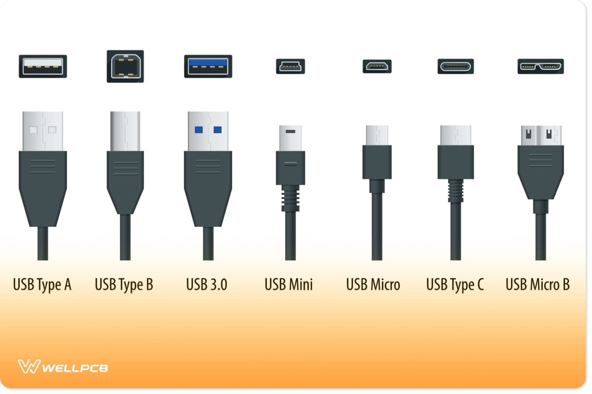
It took almost two decades for the industry to introduce a new main USB connector type – the USB type C. It was faster, more efficient, smaller, had a reversible plug, and would help support the growing trend of miniaturization.
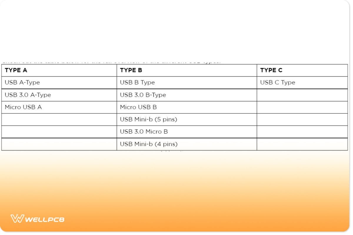
Check out the table below for a full overview of the different USB types.
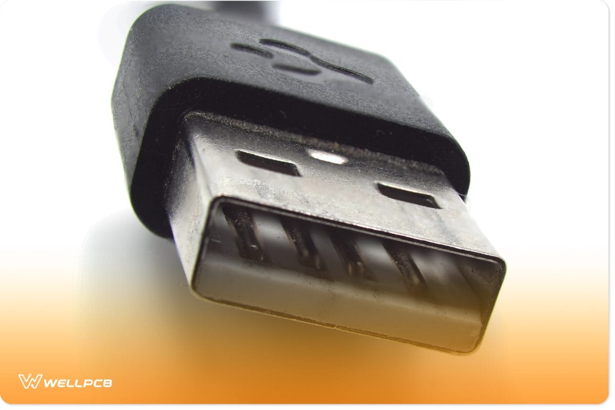
Type-A USB Connector Pinout
Type-A USB is the most widespread type of USB connector. You can find them on host controllers, computers, flash drives, and several other items.
Type-A USBs only allow downstream connections as their sole purpose is to connect to hosts.
Type-A USB connectors have flat and rectangular shapes. There are two versions of the connector: male and female. The male version is the plug, while the female version is what we know as the socket or port.
Female connector versions are what we find on host controllers, while male connector versions are usually on devices like memory sticks, keyboards, mice, and other connections to storage devices.
Type A USBs aren’t reversible. Many perceive this as one of their biggest flaws. Earlier versions could be erroneously inserted upside down and or misaligned with the plug.
Small connector housings were introduced to make it easier to align and plug USB type-A male connectors into ports.
These keys look white on USB 2.0 connectors and blue on USB 3.0 connectors.
If it’s set up correctly, a female connector’s pin header/connector housing should be located at the top of the casing.
The male is situated at the bottom (if it’s the correct way up). By locating these pin housings, and matching them, you can form a successful connection almost 100% of the time.
Applications
- Works on most personal computers.
- Also works in television and music systems.
- You can also find them on gaming consoles and almost all chargers for mobile portable devices.
Type-A USB Pinout
The older versions of the Type-A connector have four pins, while the newer versions have nine pins. Here’s a table showing all the pins of the Type-A connector.

Note: all generations of the Type-A USB connector have pins 1 to 4, while third-generation connectors have pins 5-9.
USB-B Pinout
The USB Type B is most notable for its use in printers and scanners. It has a vastly different pinout than the Type A USB connector.
It has an almost square shape with a slight bevel at the top-end corners of the connector. As with the Type A connector, it features friction to hold it in place.
The Type-B USB port is an upstream connector that you can only find on peripheral devices.
Here’s an interesting fact:
Type-B USB connectors exist to cancel out the chances of creating a connection between two host computers. Thus helping to prevent damage.
Applications
This connector mainly works for output and input peripheral devices, such as:
- printers
- scanners.
Pinout
Like the Type-A USB, the older versions of Type-B have four pins, while the newer 3.0 versions have nine pins. Here’s a table showing all the pins:
Also, there is a second type of Type-B connector that has two extra pins:
| 10 | DPWR | N/A | Power to device |
| 11 | DGND | N/A | Ground DPWR return |
USB-C Connector Pinout
The USB Type-C is slowly replacing the USB Type-B. It’s a tiny 24-pin reversible plug that works for USB cabling and devices.
Type-C USBs can serve as connectors for both hosts and devices. This means that USB-C-to-USB-C cables are available. So not only has the USB C connector replaced the Type B connector, but it’s also begun to slowly replace Type-A connectors.
It will take a while before the Type-A connection interface becomes completely obsolete though. Many Smart-TVs, Computers, and hubs still use them.
As USB-C-to-USB-C cables and adapters become more affordable, we’ll see more people adopt them.
As mentioned, USB Type C, USB 4, and the Power Delivery Specification allow up to 130W to be delivered to devices.
As such, more new-generation laptops have begun to use USB-C ports as not just a means of data exchange but as a way to power the entire device.
The Alienware x14 is the perfect example of this. Its power adapter has a USB-C connector and delivers up to 130W of charging power to the laptop.
The Alienware x14 isn’t a normal laptop either – it’s a gaming laptop. This once again proves that USB-C will be capable of acting as the main power distribution standard for future digital devices.
Under the USB 3.1 standard, the USB Type-C supports data transfer speeds of up to 10 Gbps. We’ll be able to achieve even greater speeds through the USB 3.2 and Thunderbolt3 specifications.
Applications
The USB-C type connector and standard are extremely versatile. You can find it in:
- Digital cameras
- Modern smartphones
- LCD computer screens
- Smartwatches
- Recharge earphones and headphones
- Gaming controllers for consoles and PCs
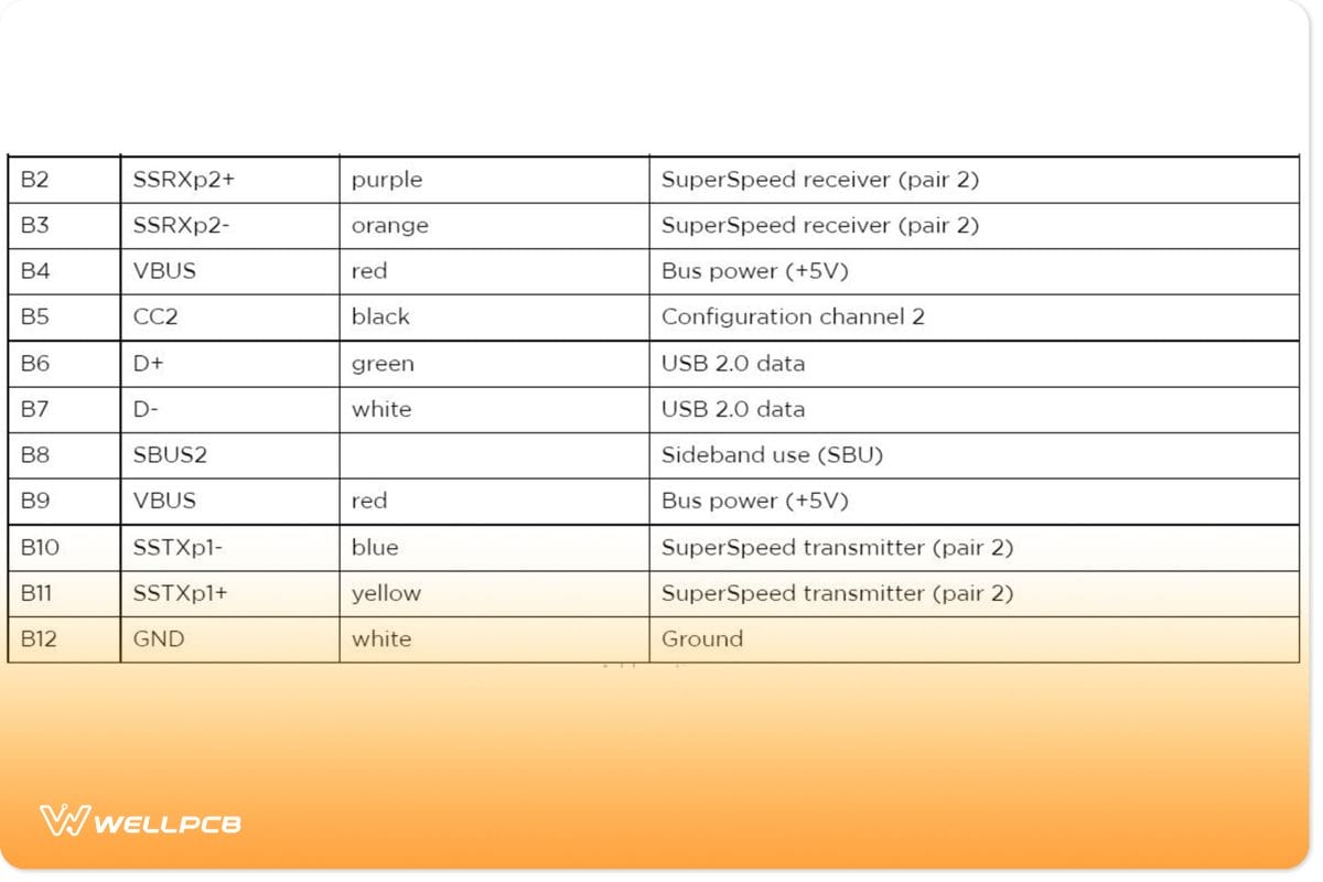
USB-C Connector Pinout
The Type-C USB has 24 pins which you can connect reversibly. Here’s a table showing the full list of pins:

Micro USB Pinout
A smaller connector became necessary as more devices required smaller USB sizes. Typical type A or B USB connectors simply could not accommodate modern mobile phones and audio devices. Thus, the micro USB was born.
Essentially, the micro USB introduced minified versions of both the Type-A (Micro-A) and Type-B (Micro-B) USB connectors. They were compatible with USB 1.1 and USB 2.0 standards, allowing them to reach data transfer speeds of 480 Mbps.
Applications
Micro-B connectors were more widespread than Micro-A connectors. Today, you can still find older devices that use Micro-B ports. These include:
- Cellphones/Smartphones
- Wireless headphones
- Portable Modems/Routers
Micro USB connectors played an important role in standardizing charging and data exchanges for portable devices before the USB-C obsoleted them. While micro-USBs are comparatively smaller than USB-C types, they’re also more fragile.
Not just the ports but the connectors, too. USB-C is a more reliable and robust alternative which means it lasts longer and is therefore more sustainable. As mentioned, the USB-C is also reversible and less finicky, which makes it ideal for people who struggle with dexterity.
Nevertheless, both the mini and micro-USB types laid the foundation for the portable connectors and ports we have today.
Pinouts
Standard older micro USB connectors have five pins, while the less common 3.0 version has ten pins. Here’s a table showing the pins of the micro USB connector:
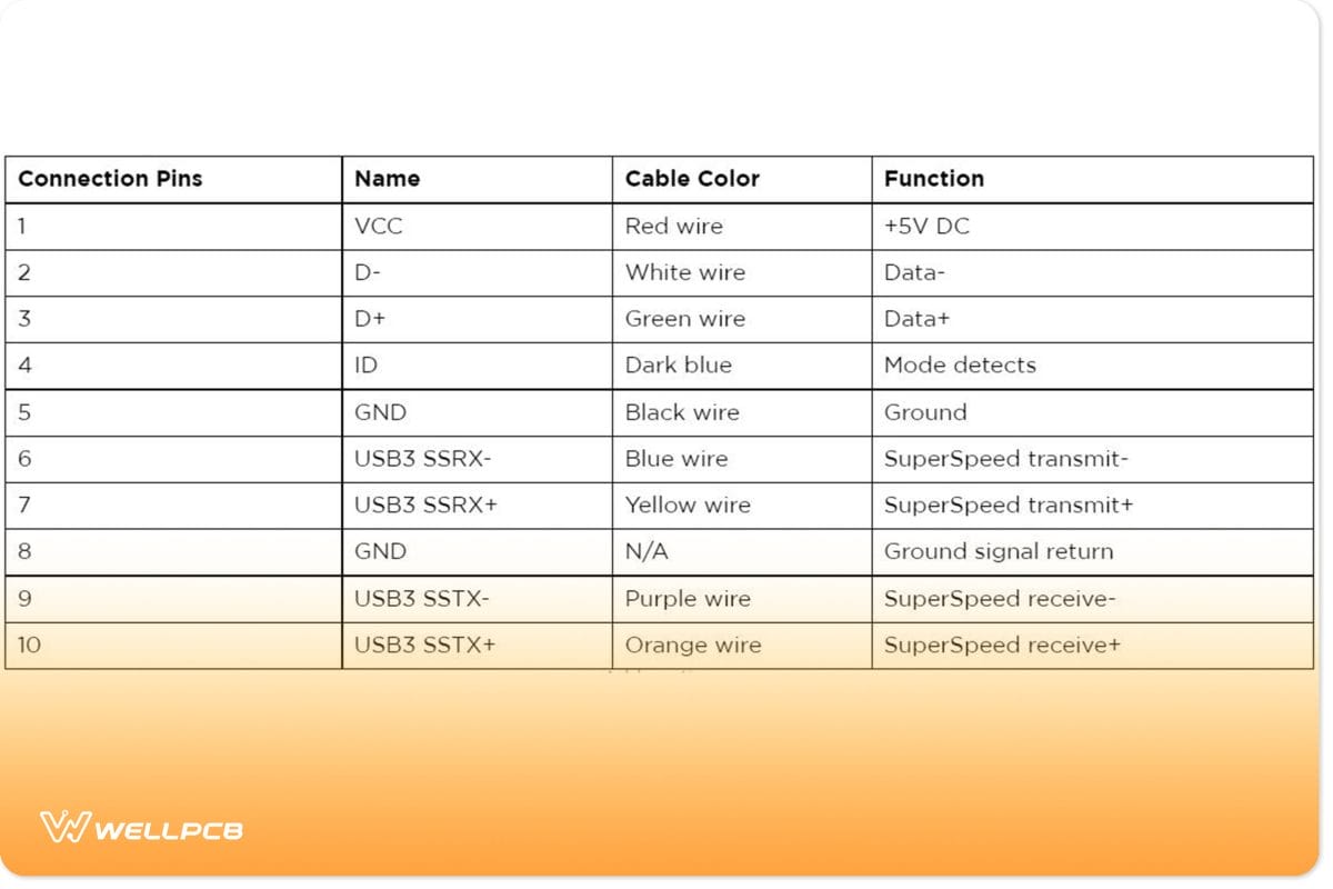
The fourth pin mode is what we call the USB on-the-go (OTG). It allows you to switch between the peripheral and host roles on your devices. It’s also what enables devices to decide which will act as a power source once connected. For instance, plugging an Android phone into a laptop. The laptop will charge the phone if you have a charge-only cable, not the phone charging the laptop.
USB On-the-Go (OTG) Functionality
Smartphones are fundamentally just pocket computers. However, people can sometimes take this fact for granted because they aren’t as extensible as conventional computers. Moreover, they rely heavily on wireless connectivity and the USB interface.
Initially, the main purpose of the smartphone’s USB interface was to facilitate power delivery (charging). Its secondary purpose was to provide a way for the smartphone to exchange data with a host device (an actual computer).
We can now use USBs to extend the functionality of smartphones and tablets in the same way we do computers. They allow us to attach external hard drives and other peripherals. However, most slave devices require a power source. Thus, the smartphone must act as a host.

This is tricky because, by all appearances, smartphones are fundamentally peripheral or slave devices. The industry introduced the On-the-Go (OTG) USB specification to address this.
In this specification, a service known as the Host Negotiation Protocol (HNP) establishes the roles of the connected devices – mainly OTG-A and OTG-B. OTG-A refers to the master while OTG-B is the slave/to-device. This configuration requires a specialized pinout to work – the USB OTG pinout.
USB OTG pinouts (Micro-AB and Mini-AB) differ from standard USB pinouts in that they have an additional pin known as the ID pin (Pin 4). The HNP uses it to determine the roles of each device in an OTG connection. The state of the pin can either be grounded (connected to GND) or left floating (not connected).
If it’s grounded, the device becomes a host. If it’s left floating, it becomes a slave/peripheral/OTG-B.
Common Issues and Troubleshooting for USB Pinouts
You’re bound to run into a few issues when working with USB ports and pinouts. Here are three common USB pinout issues you’ll likely encounter and a few solutions to address them:
- Device not recognized: Occurs when the host fails to fully detect and/or identify a connected device. This can occur when the device drivers fail to load. Or it could be an issue with your connection or cable. First, try disconnecting and reconnecting both ends of the cable (from host and device). If that doesn’t work, make sure you’re using the correct cable. You can also inspect the USB connector for any bent or broken pins. You must ensure that there are no misaligned pins. Pins from the connector and port must make the appropriate contact to establish a stable connection. It’s also a good idea to verify that the host has the latest controller and device drivers installed.
- The device is not receiving power: The device may not be charging or receiving power. First, check that the host device or adapter is undamaged and capable of supplying the device with the necessary power. If that doesn’t fix the issue, it’s likely the VBUS and GND pins on the pinout may not be correctly connected. Make sure that they’re undamaged and appropriately aligned before reseating the connection between the cable and the device.
- Data transfer issues or connection failures: These can be caused by a damaged cable or an issue related to the data pins. Check that the D+ and D- pins are properly seated. Also, verify that there are no knots or tears in the cable before reconnecting it.
If none of the above suggestions sufficiently address your USB pinout issue, then you’ll need to either replace the cable or USB port.
Make sure that you’re using the correct cable and that your device is compatible with the host’s USB version. For instance, if you have a USB 3.x cable, it’s best to connect it to a USB 3.x port.
Also, you must ascertain the connecting device is compatible with the USB 3.x standard.
How to Safely Connect USB Devices
In addition to checking the compatibility before establishing a USB connection, you must ensure that your cable is free from damage.
Damaged cables tend to cause power and disruptions which can damage the port or device.
It may be necessary to power off the device first before connecting it to the USB port. This is especially true for large (3.5”) external hard drives.
Apply gentle pressure when connecting your USB cable. Do not force the connector into the port. If unimpeded or undamaged, it should form a smooth and firm connection.
Your cable’s connector may be upside-down. In this case, you could damage the port by forcing the connector into it.
Before disconnecting a device from the host, make sure you safely eject it. Your computer, SmartTV, and OTG mobile device should have an option allowing you to safely remove hardware. Make sure you find and use it to avoid any data corruption.
Avoid connecting too many devices to a single USB hub or port extender. This may overload the power supply and damage the main USB port.
Make sure you use a good quality USB hub that can handle the power requirements of the connected devices.
It’s best to use a USB hub that uses an external power supply so it doesn’t solely rely upon the power from the main host USB.
Moreover, powered USB hubs can power high-voltage devices simultaneously. Thus, by using them, you can minimize the risk of connecting devices with high-voltage differences.
Do not attempt to connect two computers using a USB A-to-A cable as this could create a short circuit and damage both ports.
You can, however, use specialized USB-C to USB-C bridge cables to create a USB4 interdomain connection and transfer data that way.
Conclusion
A basic understanding of USB pinouts won’t just enrich you as an electronics engineer or hobbyist. It will also make you a more informed and discerning consumer.
You’ll be better equipped to identify the quality and capabilities of USB cables. When shopping for personal computers, motherboards, and smartphones, you’ll be far more considerate of the USB port selection.
For instance, because you know USB Type-C ports outperform Type-A and Type-B, you’ll prioritize shopping for devices with at least one USB-C connection.
However, you may feel that you still need help selecting the right USB connector for your project. Contact WellPCB today for expert advice on USB pinouts, connector types, and PCB assembly services.