About Voltmeter IC,Measuring the voltage between two points on your electronic circuit can provide numerous advantages. For instance, it lets you know if the electrical device, like a battery, performs as intended. Also, the voltmeter will inform you about that battery’s voltage differential. Voltmeters generally feature a special integrated circuit chip, such as the ICL7107, that helps to provide accurate measurements. Basically, these integrate on the circuit along with a seven-segment LED display.
This article describes a digital panel-type voltmeter circuit that you can utilize on any electronic device. So let’s get started!
Contents
1. What is Voltmeter IC?
A voltmeter IC provides AC or DC voltage measurements and displays the value in numeric form. In particular, many utilize Intersil’s ICL7107 3.5 ADC. And it shows readings ranging from 0-2000V at 0.1% accuracy and runs on less than 200mA. Additionally, an ICL7107’s circuitry supports display drivers, a clock, seven segment decoders, and a reference voltage source.
However, varying conditions may impact performance, including power supply voltage variation, temperature, input impedance, etc.
2. Working of Digital Voltmeter
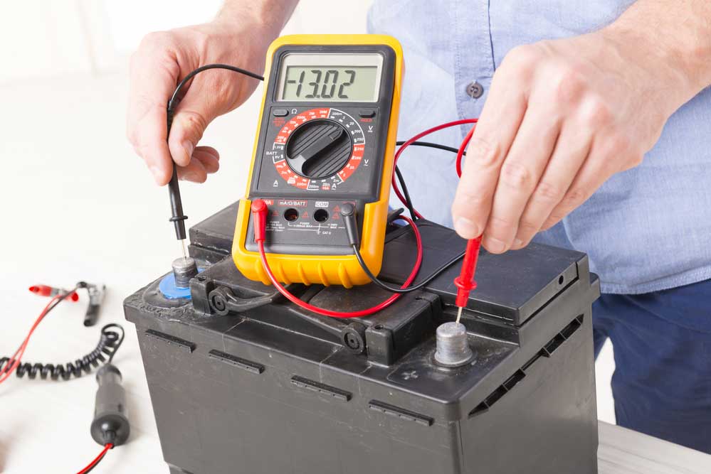
(a digital voltmeter measuring the voltage of a battery.)
Input voltage range
You should note that a digital voltmeter (DVM) has an input range from ±1 V to 1000 V. Meanwhile, a precision DVM provides 1 GΩ input resistance with a 0-20V range.
Design and working principle
A digital voltmeter’s attenuator features a series resistance, which decreases the input signal. As a result, point A voltage levels match the input voltage, Vin. With the voltage division rule, you can see that point B (R2) contains a lower voltage compared to point A (R1). Meanwhile, point C’s (R3) voltage will remain lower than both A and B.
Overall, the attenuator curtails any excess voltage to prevent it from damaging other integrated components. It undoubtedly operates as a predefined resistive network that protects an electronic circuit through attenuation. Generally, this is defined as a decade attenuation, which provides the digital voltmeter’s decimal count. Therefore, executing attenuation will result in powers of ten.
Furthermore, the ADC’s input will provide Vin/N as the input voltage:
: N = 1, 10, 100, 1000
Additionally, the circuit’s ADC provides analog to digital conversion capabilities, producing a digital output. In this case, a digital signal features two levels: 0 and 1. This process yields a series of digital pulses, and thus, one pulse equates to 1mV.
Afterward, the decade counter unit receives the digital pulses. In fact, it contains three-decade counters set up in a cascaded configuration. Each one provides 10 counts, starting from 0 to 9. Particularly, all three count to 1000.
Then, the DC 7447 performs a conversion process to display BD values on the seven-segment display. Lastly, the decimal point selector references the decimal’s position based on the voltage’s magnitude.

3. Voltmeter IC– Digital Voltmeter Types
(Various digital voltmeter types exist on the market today.)
Ramp type DVM
The ramp type DVM measures the time it takes for the input voltage to drop down to 0V. It will also measure how long it takes for the ramp voltage level to increase from 0V to the input voltage.
Dual slope integrating type DVM
The dual-slope integrating type DVM operates when switch S applies analog input to the integrator for a specific time interval. Then, the comparator’s input voltage level increases to an applicable positive value. When this fixed time interval ends, the voltage increase rate matches the input voltage.
The count configures to zero while the switch transitions to reference voltage. At this point, the integrator’s output decreases until reaching a value less than the comparator’s internal reference voltage. Afterward, a signal triggers the count to finish.
Integrating type DVM
An integrating type DVM features a voltage to frequency conversion technique. Basically, it generates pulses equivalent to the input voltage’s magnitude. Overall, this produces a series of pulses, in which its frequency relies on the measured voltage.
Successive approximation DVM
As its name suggests, the successive approximation DVM features a successive approximation converter. In that case, it performs 1000 readings per second. First, it distributes a start pulse to the start/stop Multivibrator. Then, an 8-bit control register will display 10000000. Therefore, the DAC’s output will get configured to half of the reference voltage.
Overall, the measurement cycle continues and stops when it reaches the final count.
4. How to Make a Digital Voltmeter Using ICL7107?
We included a DIY project for a digital voltmeter with ICL7107. Continue reading below to find out more!
Circuit diagram:
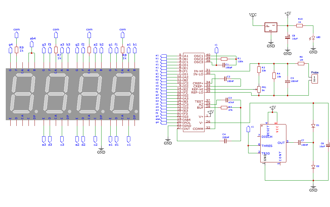
(Digital voltmeter circuit diagram)
The simple digital voltmeter circuit measures direct voltages in the 0-200V range.
Required components:
- PCB – 1x
- Seven segments LED display – 4x
- 555 IC Timer – 1x
- LM7805 – 1x
- ICL7107 – 1x
- 9V/12V power supply – 1x
- 47k resistor – 1x
- 1k resistor – 5x
- 22k resistor – 1x
- 10k resistor – 1x
- 120k resistor – 1x
- 5k potentiometer – 1x
- 100nF capacitor – 3x
- 10uF capacitor – 2x
- 100pF capacitor – 1x
- 220nF capacitor – 1x
- 47nF capacitor – 1x
- LED – 1x
- 1N4148 diode – 2x
- Probe – 1x
Steps:
Follow these steps to reproduce the circuit.
PCB Ordering and Fabrication:
This step generally involves ordering your printed circuit board online, and OurPCB offers circuit board fabrication services for this purpose.
Circuit calibration:
You will need to power up the circuit and short all input terminals. Afterward, fine-tune the R6 resistor until the display shows 0V.
Connecting the components:
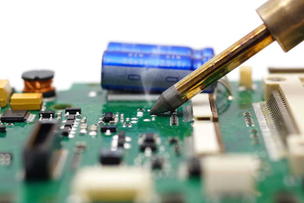
(You will need to solder the details on the circuit.)
First, connect the ICL7107, IC 555 oscillator circuit, and all the components as shown in the circuit diagram. Then, add the four seven-segment LED displays and connect them as shown. Next, integrate the LM7805 into the circuit. You will also need to connect the GND pin to the ground. Afterward, connect the IN pin to VCC and the OUT pin to the R10 1k resistor. Then, connect that resistor to the LED, which connects to the ground. Additionally, connect the C8 10uF capacitor’s positive end to the OUT pin and negative lead to the ground.
Summary
To summarize, a digital voltmeter circuit helps ensure that your device works properly. It achieves this by measuring two voltage points and producing a digital number. Of course, that number must go through a conversion process before it shows up on the seven-segment LED display. After that happens, the number will appear in digit format, which represents the input voltage. Overall, digital voltmeters have proven helpful for professionals and anyone creating their projects.
Do you have any questions regarding the voltmeter IC? Feel free to contact us!


