Contents
What is SCR
SCR (silicon control rectifier) is a special thyristor with ON-OFF switching capabilities through bias conditions or gate input control. Its symbol looks identical to a diode. As the name suggests, it comprises silicon that controls power and transforms AC voltage into DC. Additionally, SCR sees more implementations than other thyristor types, including TRIAC, SCS, and DIAC. These integrate on an AC circuit.
Generally, the four-layer PNPN SCR semiconductor consists of three junctions (J1, J2, and J3). You will find J1 between the first P and N layer, J2 between the N and Player, and finally, J3 between the last P and N layer. Three terminals secure the anode (positive electrode located on the upper P-layer), cathode (found on the N-layer), and gate. Moreover, the entrance serves as the SCR’s control terminal. Both external P and N layers undergo heavy doping, while the central P and N layers undergo light doping. Then, the gate terminal attaches to the central P-layer. Current can flow through this unidirectional device in one direction and soak in the opposite direction.
Additionally, this device features high operational speeds, longevity, high voltage, current handling capabilities, and power gain.
How SCR works
Silicon-controlled rectifiers operate in the same way as a diode: blocking reverse current and conducting forward current. It also withstands high voltages. Furthermore, this device contains a gate to conduct forward positive current through the anode (A) terminal. Applying a short control pulse to the gate will cause the SCR to become conductive between the bridge path (anode to cathode). When that happens, anode current flows through it until the value reaches zero, forcing the SCR to switch off. Then, the gate will need to receive another voltage control pulse to make it conductive again. Otherwise, it will not require more gate voltage once it conducts.
An SCR also operates in three modes: forward blocking the way, forward conduction mode, and reverse blocking. However, the voltage rating remains the same for on and change blocking methods.
Triggering the SCR to switch ON occurs in varying methods. They include voltage triggering, thermal triggering, light triggering, and DV/DT triggering.
Voltage triggering

(Applying voltage causes the SCR to activate)
The first one, voltage triggering, involves applying a voltage higher than the maximum point, causing the terminal gate to open. However, implementing this approach could cause permanent damage to the device. That’s because an SCR controls the voltage’s high values, which will fail to perform while the gate remains open.
Thermal triggering
Thermal triggering will also cause the device to conduct as its temperature increases. In effect, the hole and electron pairs will enlarge. As a result, the regenerative current increases, forcing the SCR to activate. However, this triggering technique could cause thermal runaway.
Light triggering
Meanwhile, light triggering involves beaming light onto the SCR’s surface, causing the electron and hole pairs to multiply. This forces the device to activate.
DV/DT triggering
A high voltage rate between the anode and cathode will also switch the SCR ON. However, the rapid current increase could break the device. Therefore, we recommend implementing protection for this approach.
SCR Applications
SCR as a Switch
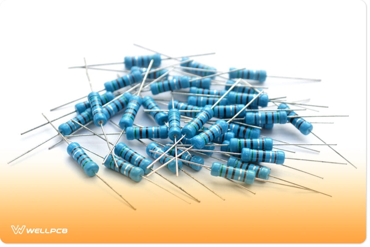
(Resistors protect the diodes on an AC breaker circuit)
This application involves utilizing two SCRs, which create and break a circuit. AC input voltage distributes regulating trigger pulses to the SCR gates. Two resistors keep both diodes safe while resistance administered to the gate reduces the current. The circuit starts during the switch’s closed state. Then, SCR1 triggers during the positive half-cycle due to its forward-biased state. If the current value reaches zero, the device will deactivate. After that happens, SCR2 fires because of the reverse voltage polarity, and it receives the correct current. Opening the switch causes the circuit to break. In effect, the SCRs will no longer receive trigger pulses while the current is set to zero.
Therefore, a traditional switch can handle a gate current’s mA, which means that it can activate/deactivate the load current.
Over-voltage protection
(An SCR can provide over-voltage protection on a circuit.)
Due to its quick switching ability, an SCR keeps other electronic components safe from over-voltage. These must connect in parallel with the electrical load. When excess voltage occurs, the SCR’s gate activates. Then, it draws current from the power sources, which lowers the electrical load’s voltage. Implementing two SCRs provides the best results for this scenario. The first one focuses on the positive half-cycle, while the other focuses on the negative half-cycle. A resistor lowers short-circuit current during both SCR triggering processes. Connecting a Zener diode in series with each resistor forms a circuit that can detect high voltage.
Pulse circuits

(An electronic ignition utilizes an SCR.)
An SCR also provides applications for high waveform voltage and current pulses on a circuit. A capacitor charges during the main supply’s positive half cycle. From there, the SCR switches ON via the negative half-cycle. The SCR switches OFF when the capacitor discharges and the forward current reaches zero. Afterward, the ON process will repeat, causing the output pulse frequency to match the supply’s frequency.
Different Types of SCRs
Discrete Plastic: The discrete plastic SCR type contains three pins mounted to a semiconductor plastic covering. Furthermore, these integrate on a PCB, available from 25A to 1000V.
Stud Base: Easy to attach, this unit consists of a screwed base and provides low thermal resistance. Additionally, the stud base device supports 5 to 150A of current along with full voltage.
Plastic Module: This consists of more than one device while providing the same qualities as the discrete plastic. It can handle up to 100A and attach to a PCB with a bolted heatsink.
Press Pack: These press pack SCRs are enclosed in a ceramic along with the electrodes to seclude the anode and cathode. They also offer support for 200A or higher and applications requiring over 1200V.
Flat Base: A flat base comes with insulation, keeping it safe from the heatsink. With similar qualities as the stud base, this can handle current measuring from 10 to 400A.
Modes of Operation in SCR
Forward Blocking Mode:
The SCR functions in forwarding blocking mode when its anode receives positive voltage and the cathode receives negative voltage. This forces a small forward leakage current to pass through the device.
Forward Conduction Mode:
In forward conduction mode, the SCR switches on, causing it to conduct current from the anode to the cathode. This occurs from applying a voltage to the gate or exceeding the forward breakdown voltage.
Reverse Blocking Mode:
Applying positive voltage to the cathode and negative voltage to the anode puts the SCR in reverse blocking mode. In effect, Junctions J1 and J3 shift to reverse bias while J2 sets to forward bias, preventing current flow throughout the SCR.
SCR circuit diagram
How to test SCR
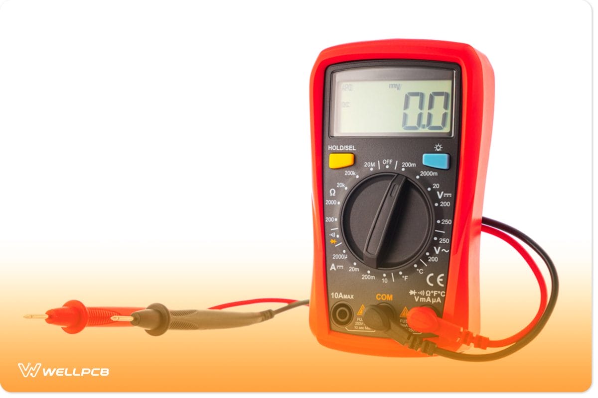
(Use a multimeter to test the SCR)
An SCR testing approach involves utilizing a multimeter, an effective process. To start, you will need to set the multimeter switch to high resistance. Then, join the multimeter’s positive wire to the SCR’s anode gate and the negative wire to the cathode. After following that step, the multimeter will indicate an open circuit. If you switch the connections around, it will also display an available course.
Next, hook up the SCR’s gate terminals and anode to the multimeter’s positive end. Afterward, you will need to connect the SCR’s cathode to the opposing end. In effect, this causes the multimeter to display a low resistance reading, which means that the SCR’s switch is set to ON. Removing the anode’s gate terminal will output the same task, representing a latching form. Positive testing results mean that the SCR provides high-quality performance.
Summary
After all, an SCR hosts practical applications for simple circuits. Not only that, but it can also protect components against over-voltage. It also acts as a rectifier, converting AC to DC while controlling power. That alone makes this device a necessity. Furthermore, it comes in a few types that serve their purpose with beneficial features. Lastly, an SCR operates in three different modes, making it a complex device. It requires applied voltage to provide switching capabilities.
Do you have any questions regarding a silicon control rectifier? Feel free to contact us!
