
Undeniably, windmill generators are fast replacing solar power panels. It is because windmills are reliable, efficient, and work at any time of the day. Furthermore, it solely depends on the energy in the wind, which, luckily, is available throughout the day. Also, compared to coal plants or fossil fuels, the wind industry has a generally low environmental impact as an energy source.
Therefore, in today’s article, we will use a simple windmill power diagram to construct a windmill generator circuit. Often, you will find the DIY wind project to be cost-effective and reliable. What’s more, you can also have wind turbine applications such as charging your electrical appliances and batteries at any time.
Contents
1. How does a wind turbine work?
First, we should know that a wind turbine’s installation position plays a role in its working and electricity distribution. For example, a wind turbine location near shores, seas, or higher altitudes has greater working efficiency because of reliable wind energy. At most times, the distance can be about 100 meters above the ground.
Major wind turbine parts
A wind turbine should have the following to help in efficient working;
Generator; it powers up the turbine by producing 60-cycle AC electricity. The most commonly used electrical generator technology is the doubly-fed induction generator (DFIG).
Rotor blades; are often two or three structures with airplane wing shapes. And, when the wind blows over them, they lift and rotate then, causing the rotor to spin.
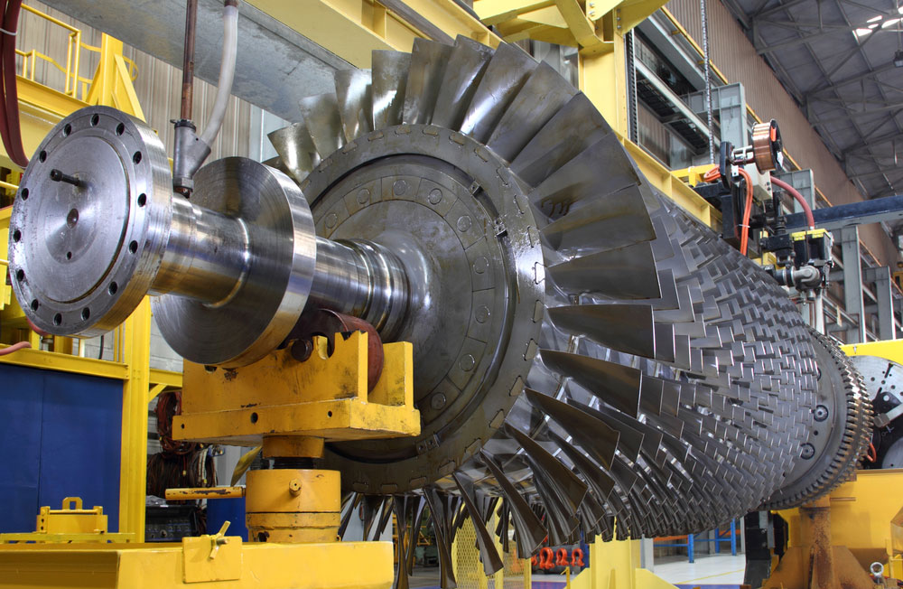
(a turbine rotor)
Electric or mechanical brake; during emergencies, the brake can hydraulically, mechanically, or electrically stop the moving rotor.
Gearbox; It is the connection between the high-speed shaft and low-speed shaft. It also functions to augment the rotational wind speed from around 30-60 rpm (rotations per minute) to 1000 – 1800 rpm. Often, turbines work within the mentioned average wind speed for electricity production.
Nacelle; It majorly contains some wind turbine components such as the gearbox, brake, and controller.
Controller; the role of a controller is to start the turbine at 8 – 16 mph (miles per hour), then stop it at 55 mph. It is because a wind capacity higher than 55 mph speed can damage the machine.
Tower; its structure, made from concrete, steel lattice, and tubular steel, is strong enough to support the turbine’s structure. Furthermore, you can yield more electrical power with increased tower height.
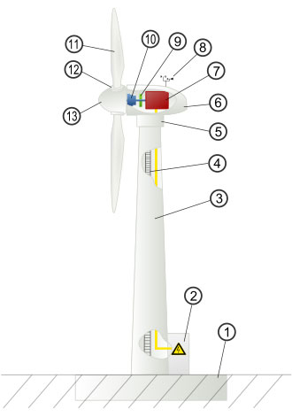
(parts of a wind turbine)
Working process;
- First, when the wind flows across the rotor blades, there is a reduction in air pressure on the opposite side of the rotor blade.
- Then, due to the air pressure difference on the two sides of the blade, there’s both a lift and drag motion.
- The rotor begins to spin because the lift force of the turbine is more potent and more significant than the drag.
- The rotor either has a direct connection (in drive turbines) or an indirect connection (via a gearbox or shafts) to the generator. Consequently, it speeds up the rotation.
- In summary, the turbine will have converted the kinetic energy in the wind to mechanical energy then to electrical energy (via generators). You can further understand it as wind power generation following aerodynamic forces from the turbine blades to the generator’s rotation.
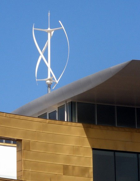
Note; different types of wind turbines will have varied functions. For example, a horizontal-axis wind turbine (such as the ones in offshore wind farms) has the axis of rotation in a horizontal plane. On the other hand, vertical-axis wind turbines have their rotation axis in a vertical plane. Therefore, it is easier for VAWTs to capture a high wind energy capacity from any direction without having the rotor reposition its state.
(a vertical axis wind turbine)
2. Windmill Power Diagram– How to Design and Create a Windmill Generator
Let’s first understand the working principle of a windmill power diagram before embarking on the construction.
The working principle of Windmill Power Diagram design
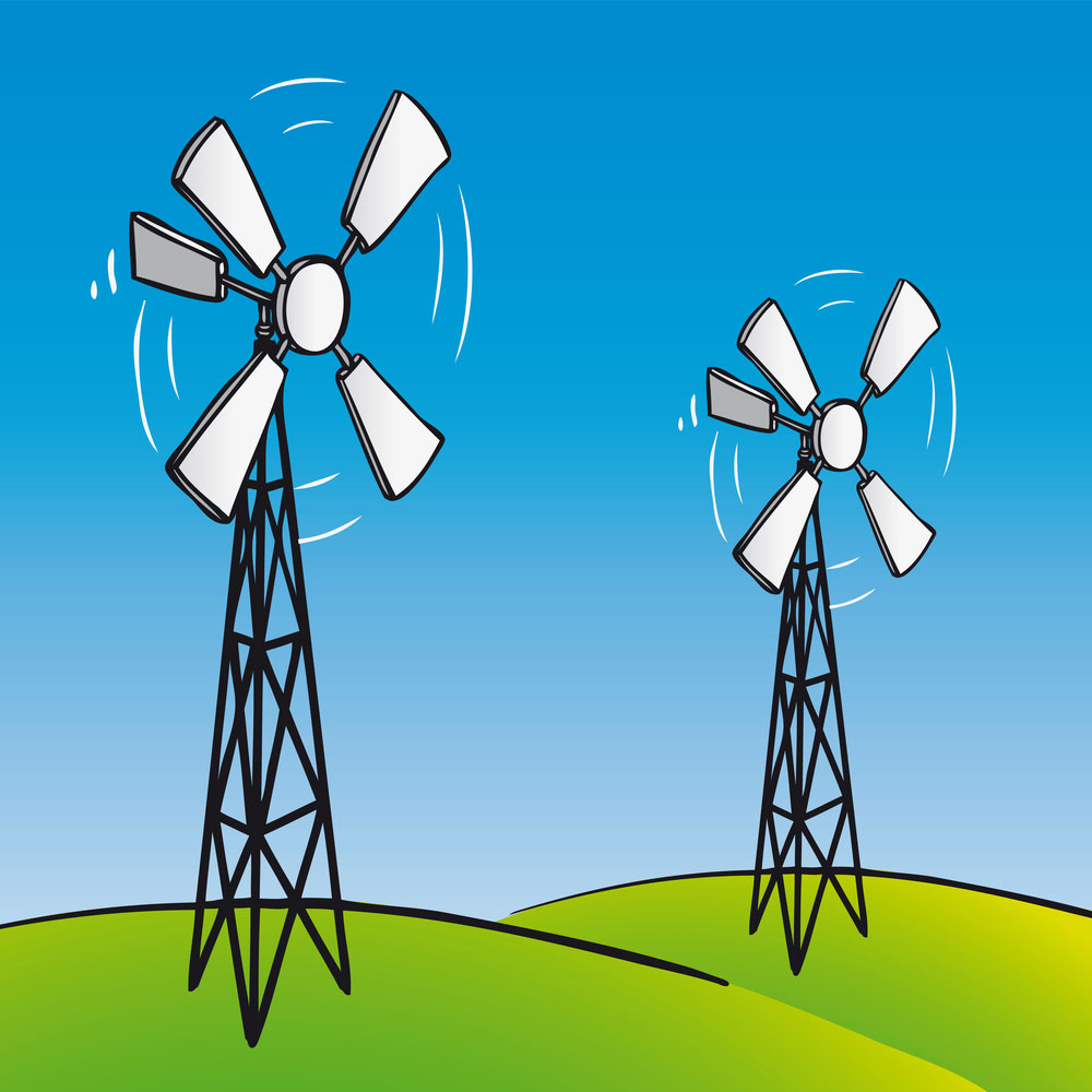
Generally, windmills base their principle of operation on a concept of a traditional motor-generator. In other words, the operation concept involves integrating a motor spindle (permanent magnet type) with a propeller/ turbine. However, instead of a traditional propeller of an airplane type, wind turbine manufacturers now use an S-shaped propeller system because it is advantageous.
(old/traditional windmills).
Also, the current design of the turbine rotation doesn’t automatically work on the wind direction; instead, it responds depending on any side of the wind flow. As such, the modern wind turbine system can do away with the complex rudder mechanism. What’s more, you will effortlessly and effectively get electricity from wind power year long since the windmill isn’t limited to a specific flow of wind direction.
Windmill Power Diagram– Material preparation
The materials you’ll need include;
- A generator,
- Blades,
- Tower,
- Batteries and diodes,
- A motor,
- The turbine body, and
- The central hub.
Steps in a windmill power diagram
Step 1: First, begin by getting a generator. For the project, we will be using a Direct current motor since they make great wing generators.
Step 2; Then, you can curve the wind turbine blades from the wood. Alternatively, you can also cut PVC pipe sections then shape them into airfoils.
Step 3; Thirdly, proceed by building the rotor hub where you’ll attach the motor then add the blades. Again, ensure the diameter is fitting.
Step 4; Further, make the mounting for your turbine by strapping the motor to a piece of wood.
Step 5; Next, using plywood, cut a 2-foot diameter then, make a tower base.
Step 6; Do some painting on the wood parts to prevent them from getting damaged in the harsh weather.
Step 7; Afterward, focus on the machine’s electronic component, i.e., the charge controller that runs every operation. Other electrical features include batteries, blocking diodes, and secondary load. You can also choose to buy the controller.
Step 8; Erect the wind turbine and tower.
Step 9; Finally, connect the machine to the electronics and enjoy your hard-earned electrical power.

3. Windmill Power Diagram– Problems in the Production Process and How to Solve them
A few challenges that can arise when constructing your windmill can be;
1. Windmill Power Diagram– Fluctuating wind speed
Inevitably, wind speeds often fluctuate at particular points of the day. And so, to solve the problem, you can use a buck or boost converter circuit. For example, let’s say the generation capacity of the windmill motor output is 12V. With an additional boost, the buck circuit can increase its voltage to more than 60V. However, you have to restrict the voltage and have it at a stable output.
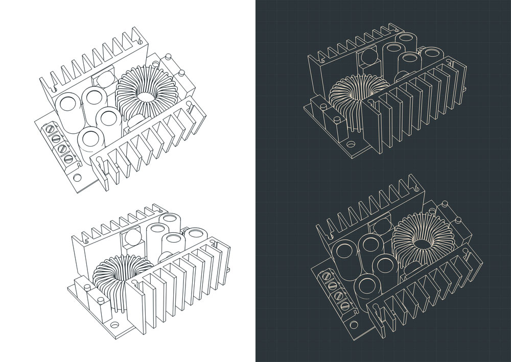
(blueprint of a buck converter module)
Windmill Power Diagram–Noise and aesthetic pollution
Despite the turbines and wind power plants having a minimal environmental impact, they can still cause noise pollution and visually affect the landscape. Thus, turbine constructors are now using several small-scale or scattered wind turbines to reduce the visual impact problem. On the other hand, sound requirements ensure the wind technology isn’t nearby residential areas.
Summary
To sum it up, in case you wish to start up a wind farming project, then the post we have for you today will guide you through the windmill power diagram process. What’s more, if you need a large-scale wind project, you won’t have to go through the process alone. You can include specialists, such as environmental scientists, atmospheric scientists, construction equipment operators, construction laborers, and many more. They, in turn, will help you with wind resource assessment, among other things.
But do remember, you can contact us if you need clarifications or if you have questions.


