Contents
Wireless Battery Charger Circuit Principle
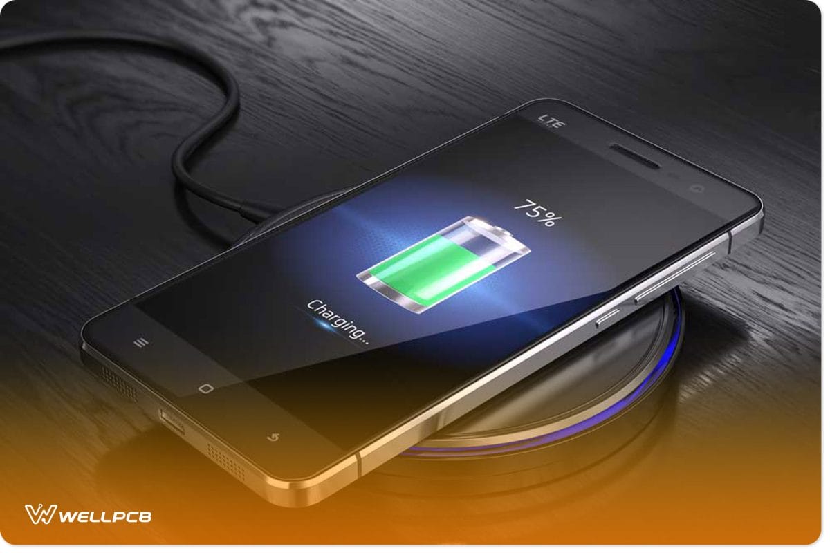
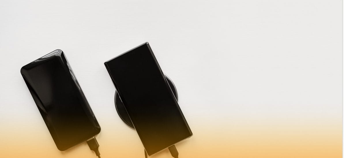
Fig 1: Wireless charging of a smartphone
The wireless battery charger circuit works on the principle of mutual inductance or power transfer through inductive coupling. Generally, we have three types of wireless charging systems.
These are:
- Charging pads using tightly-coupled electromagnetic non-radiative or inductive charging.
- Charging bowls using radiative or loosely-coupled electromagnetic or resonant charging. They’re capable of only transmitting charge a few centimeters.
- Uncoupled RF (radio frequency) wireless chargers with trickle charging capability. They’re more powerful and can allow trickle charging to distances of many feet.
Now, let’s look at the general circuit principle of a wireless battery charger.
Wireless charging relies on magnetic resonant coupling to transmit electricity between two devices. Magnetic resonant coupling uses a transmitter coil that creates a magnetic field and a receiver. When you connect your wireless charger to electricity, it converts it into HFAC. HFAC (high-frequency alternating current) transfers to a transmitter coil through the charger circuitry, creating a varying magnetic field.
When you place your device with a receiver coil close to the charger, the magnetic field gets coupled to the device’s circuitry. The result is that the varying field induces an alternating current (AC) in your device’s circuitry. The AC is then converted to Direct Current (DC), which charges your device.
How To Make a Wireless Charger Circuit?
Schematic
Here’s a wireless charger schematic:
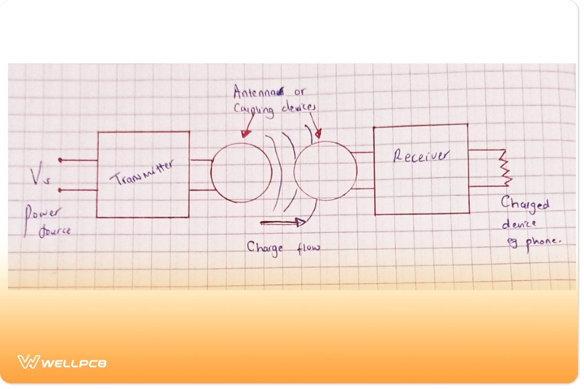
Fig 2: General wireless power transfer schematic
What Do We Need?
- 1 mm thick wire (7 m)
- 1 Dot PCB Board
- One 10K trim pot [103]
- One 555-timer IC
- 10-ohm resistors
- 10k resistors
- Screw Terminals
- 1 Mini USB connector [male]
Creating The Coils
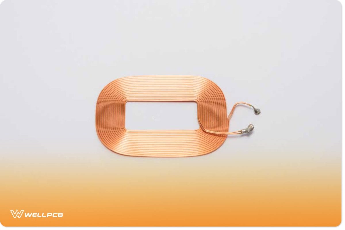
Fig 3: A copper coil
It isn’t easy to wind a perfect spiral without the right start. Therefore, you can choose to cut a small section of cardboard 1 cm in diameter and glue it over a flat surface. Apply glue on the area close to the circle (hold the windings in position). Afterward, wind the 1 mm thick wire around the circle until you get 30 turns. Make two identical coils.
Make a Measure
Use an LCR meter to get the coil’s inductance. For example, the 1.0 mm diameter wire with 30 turns should give you a 21.55 to 26.07 uH.
Next, use the formula F = 1 / (2*pi*sq-rt(LC)) to get your circuit’s resonant frequency. In our setup, L is 26.07 uH, and C is 47nF, leading to an F of 143.78 kHz.
The Oscillator Circuit
Here, use a 555 timer IC to generate a 143.78 kHz signal to drive the LC circuit.
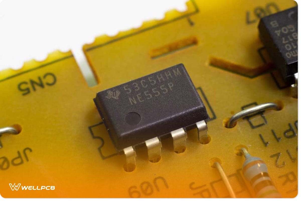
Fig 4: A 555 timer IC
Testing
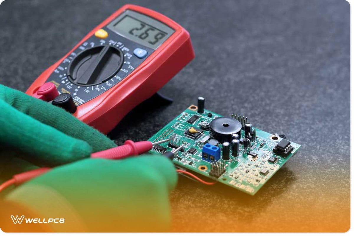
Fig 5: Testing an electrical circuit using a multimeter
Here, measure the 555 timer IC’s third pin while adjusting the 10K trim to get your 143.78 kHz frequency.
Next, use a multimeter to measure:
- Vin (check if its 12V)
- Current input (Iin) from the 12V line
- Vout (should be precisely 5V)
- Current output (Iout) from the buck converter to mobile.
Afterward, find your circuit’s efficiency using the formula Efficiency(n) = Pout / Pin. Pin = input voltage (Vin) * input current (Iin) and Pout = output voltage (Vout) * input voltage (Iout).
From our set-up, we have Vin = 11.8V; Vout = 5.1V; Iin = 310 mA; Iout = 290 mA. We then have a 40.4% efficiency.
Make Enclosure for Circuit Board
Make a cardboard enclosure for your wireless charger using cardboard.
Fix the Circuit on the Base
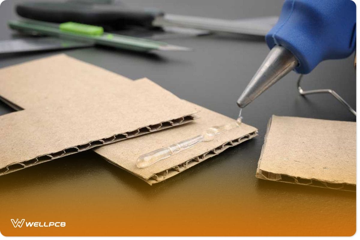
Fig 6: Applying hot glue on a cardboard
Apply a double-sided tape or hot glue to the base of your cardboard. Next, fix your wireless charging circuit board onto the tape or glue.
Reconnect the Coils
Reconnect any loose coils and make sure that they’re working well.
Enclose the Coils
Cover your enclosure with circular cardboard and secure it with glue.
Testing
When you flip on the switch, you’ll see the status LEDs alternate between red and blue before returning to their initial red color. Placing a mobile phone close to the charger turns the LED blue, indicating it’s charging.
Conclusion
As we’ve seen, the working of a wireless charging circuit is simple and implementable. Also, the charger is robust and cheap to build using locally available materials. If you have doubts, worry no more and start working on your project.
Finally, contact us for assistance or clarification. We’ll get back to you as soon as we can.


