Contents
What is a Yagi Antenna?
A Yagi Uda type of antenna is a hemispherical antenna, but just like many others, designed to transmit FM signals.
The geniuses behind this form of the antenna are Shintaro Uda and his friend Hidetsugu Yagi. Hence the name Yagi Uda antenna.
A Yagi Uda is suitable for FM signals because it can trap and transmit over a long line of distance. This transmission distance can cover up to 5km in length using an RF power of 1W.
The yagi antenna, unlike other antennas, is smaller in size. As a result, its gain capability is profound.
Also, it is made up of only a group of rods called the parasitic elements.
These parasitic elements ensure the efficiency of the antenna.
The elements include the reflector element, single or more director elements, and the dipole element.
The arrangement of these elements needs to be accurate because they help to give the antenna a directional pattern that the single antenna often lacks.

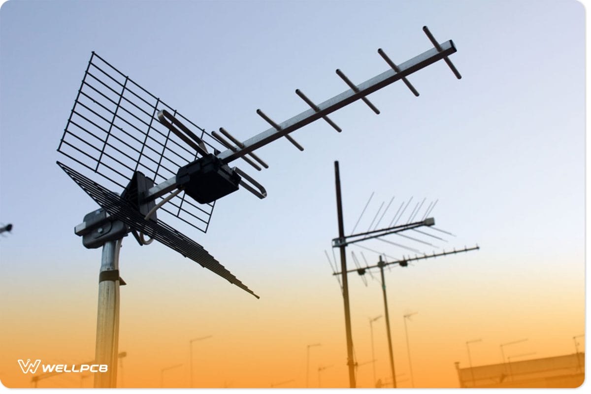
(a Yagi Uda antenna close to a satellite dish.)
Yagi Antenna Design Formula
We should consider specific physical parameters when designing the Yagi Uda antenna type.
Notably, the length and spacing of these antenna rods should be our top priority in antenna construction.
The Yagi antenna can collect different frequency signals as specified by the designer.
Moreover, we can design an antenna for a specific frequency by using lengths and spacing measured in wavelength. Additionally, the frequency to use determines the size and the bandwidth narrowing we will use.
(a well-designed antenna)
The reflector
We often find the reflector behind the other two elements. It is usually 5 percent longer than the active, driven element.
Notably, between 0.1⋋ and 0.25⋋ is the amount of spacing we can have between the driven element and the reflector.
Any distance outside this limit will disrupt the signal strength. Moreover, this spacing can sometimes be dependent on the frequency-to-bandwidth ratio and the specifications of the sidelobe pattern.
The bandwidth, DB of gain, feed impedance, and front-to-back ratios are essential specifications we consider in a Yagi antenna development.
Also, these can be the input values in the Yagi antenna calculator.
The dipole
In the middle of the driven element is where you will find the feed point. The feed point is another name for this antenna piece.
We call it the feed point because the transmitter’s feedline meets the receiver’s feedline. Importantly, this feedline aids in frequency transmission from the transmitter to the antenna.
Sometimes, these antennas have a folded dipole.
This feature increases the relay impedance. However, the antenna develops a resonant frequency when the electrical length is about half the frequency wavelength.
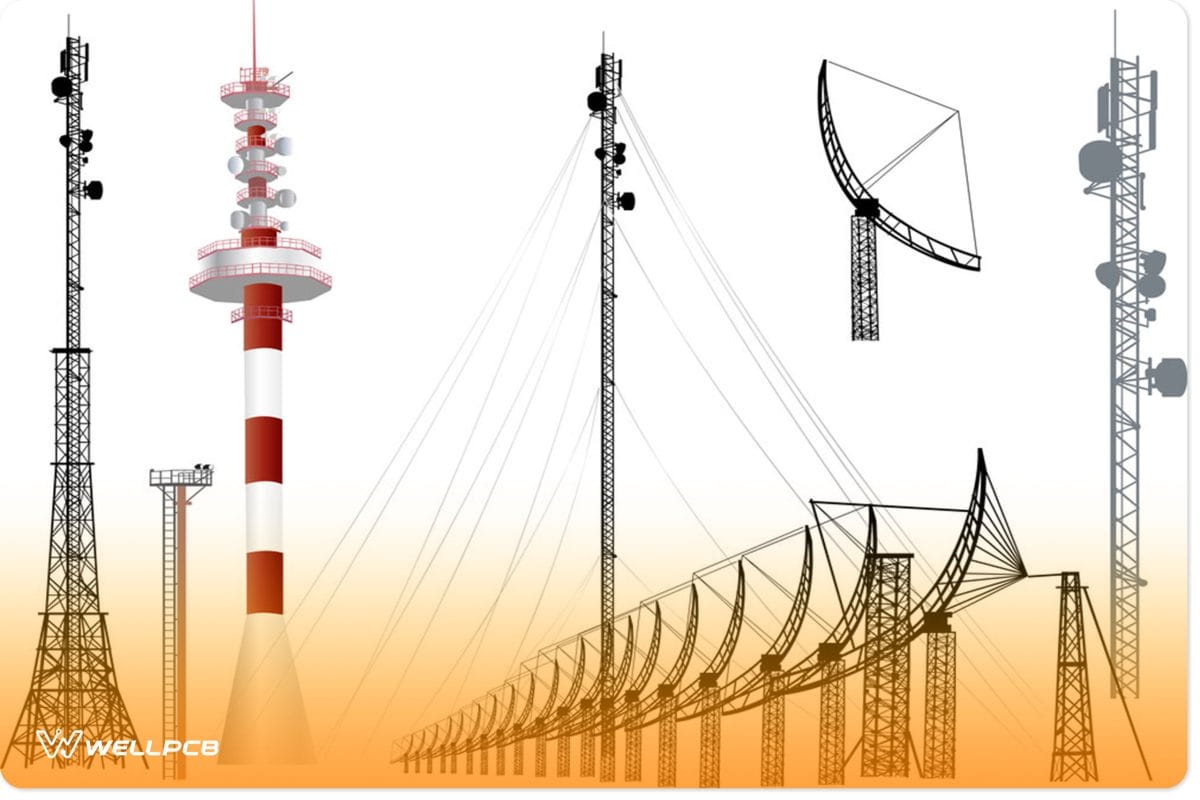
(Antenna Icon set)
The director
It is easy to pick out the director because it is the shortest of all the other elements. Importantly, we place it at length 5% less than the active, driven element.
The primary purpose of the director elements in the antenna is to receive electromagnetic frequencies when within an electromagnetic field.
However, the director has a higher resonant frequency than the driven element.
In addition, the director helps to attain a directional pattern and the desired gain.
This property makes the Yagi Uda work as a directional antenna.
As discussed earlier, the Yagi Uda antenna can have one or more directors. The multiple directors are one of the antenna’s advantages. Significantly, the separation between the directors ranges between 0.1⋋ to 0.5⋋.
However, the number of directors we use does not determine the gain for directors in Yagi, but the antenna array’s length does.
For example, with a very high-frequency field of 200MHZ, the approximate figures of the elements measured as follows from the Yagi antenna calculator;
- reflector length= 150/f =150/200 =0.075m
- driven element length = 138/f = 138/200 =0.69m
- dipole length
- dipole to director spacing
- reflector to dipole spacing
- first director length = 140/f =140/200=0.7m
- second director length = 136/f = 136/200 = 0.68m
- length of boom
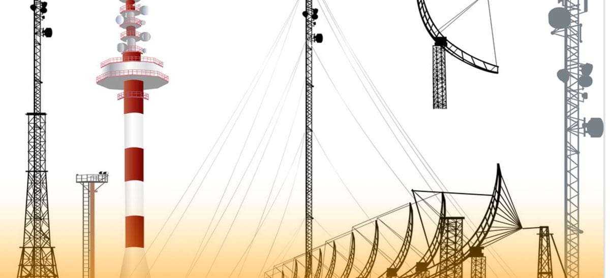
(Collection of antennas)
Yagi Antenna Design Software
We have various software that can assist in designing this antenna. This article will talk about the Yagi Designer 2.0 and the MS-DOS Antenna maker.
The Yagi Designer 2.0 is a Yagi antenna calculator that displays many features.
These characteristics of antennae can include the horizontal radiation pattern, the vertical radiation pattern, the E-plane, H-plane.
Also, the feed point resistance and reactance, as well as the antenna gain considerations F/B ratio, are features you’ll need in this software.
On the other hand, the MS-DOS software has quicker and more accurate dimension calculations.

(a photo of a transmitter.)
How to Design a Yagi Antenna
Using a 300MHz operating frequency and a single director, we will do an entire antenna construction of a Yagi-Uda.
You should know that you can manually conduct the calculations using the integral equation or easily feed them into the software.
However, the software should undergo prior detailed optimization where you provide the software or Yagi antenna calculator with the initial data.
We use a speed velocity(v) of 180,000,000m/s and a frequency(f) of 300MHz. So, we calculate lambda by having the speed ratio to the frequency(v/f).
Also, use the reflector length of 0.495⋋, the dipole length of 0.473⋋, 0.440⋋ of director length, and the reflector to dipole spacing of 0.125⋋. These are the initial values we feed to the software or the Yagi antenna calculator.
Then, the 3-element Yagi antenna calculator or the software does the calculations. It replaces the v/f, which we find approximately 1.67 from the earlier equation.
Unquestionably, using these formulas will easily find the correct antenna parameters and element lengths to use. Accurate dimension distribution is necessary to increase the antenna performance.
It is easy to design this primary antenna at home. Besides, an antenna with aluminum pipes can work perfectly only if we get the measurements right.
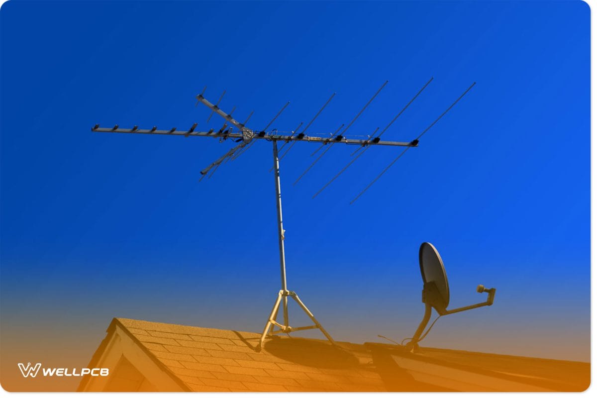
(an antenna with more than one director.)
Yagi Antenna Application
- Yagi antenna is a form of RF antenna we use to transmit a radio wave beam.
- Polarization places this antenna under a hemispherical antenna. Radio astronomy requires the presence of these antennas.
Summary
The Yagi Uda antenna is one of the best and most commonly used antennas in the market.
We often find it in households and offices because of its small size and efficiency.
We hope this article has helped you learn about antennas. Be sure to check out some of our other pieces from our website.
Otherwise, please get in touch with us for any queries regarding this topic or help!