PIC16F877 has many features that make this microcontroller great for beginners and professionals alike.
PIC16F877A contains everything PIC16F877 has and includes an internal clock oscillator, a better working analog to digital converter module(ADC), and more!
This article will discuss the PIC16F877 microcontroller features and introduce you to the input/output port and simple connection. It will help you understand these circuit devices and how to use them.
Contents
1.PIC 16F877 Overview
PIC16F877 means that this PIC microcontroller can perform several tasks with the help of software.
The design of PIC 16F877 is for use as standalone or as an addition to other devices’ circuits. For example, RAMPS and Arduino boards. It can also work on its own. But, if you want it to do so without problems, you need to have a crystal oscillator (frequency).
PIC 16F877 is a fully static device, which means that it works with a limited amount of flash and RAM. Moreover, it has excellent operational flexibility, is cheap, and is the most common in circuits.
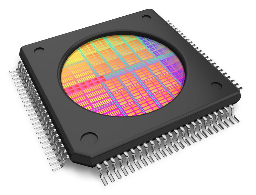
(Microcontroller)
2. Features Of PIC 16F877
(Microchip)
The general features of PIC16F877 are;
– Power saving STOP mode, which means that you can stop PIC16F877 without removing it from the circuit
– High-speed PWM(Pulse Width Modulation) module can generate up to 256 levels of output and has an in-built clock programmable Prescaler
– One internal voltage regulator for the I/O circuit and an integrated oscillator (crystal or ceramic resonator)
– One on-chip comparator module
– Analog to digital converter, with a resolution of 12 bits and can convert up to four analog input channels simultaneously
– Supports external interrupts used to wake the device from sleep mode or for any other purpose.
– Eight different power save modes

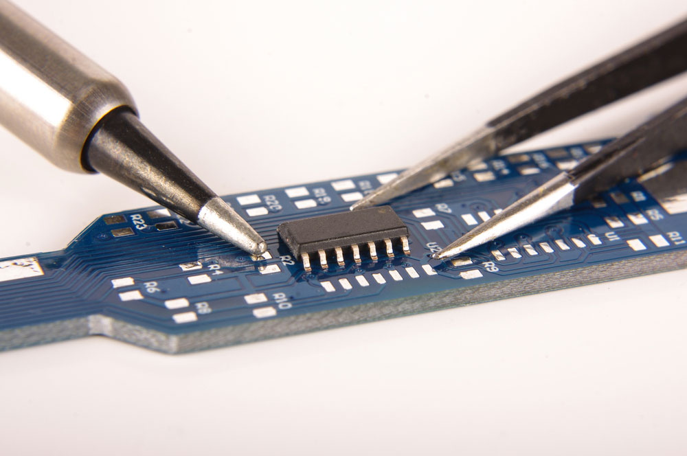
(Disassembled Microcontroller)
– Analog comparator module
– Up to 23 I/O pins
– One SPI mode and four UART modules (one full-duplex)
– Interrupt controller with up to 14 interrupt sources
– Watchdog timer, which generates an interrupt if the time interval expires
– Power-on reset generating circuit
– Programmable brownout detector(BOD)
– Internal calibrated oscillator, which allows the internal RC circuit to work as a clock source
– In-circuit Serial Programming and in-circuit debugging capability via the debugWIRE interface
(Microcontroller)
The main/key features of PIC 16F877 are:
- Up to 20 MHz internal clocks operating frequency
- Has five (A-E) basic input/output ports
- 8 10-bit \ADC input channels
- Has PSP as its parallel communication
- PIC16F877A has 8KB Flash memory
- Two serial communication interfaces: 2-wire Inter-Integrated Circuit (I²C™) bus and SMBus
- 368 levels Data memory bytes with 256 levels (14bits) EEPROM Data memory
- Has three timers i.e one 16-bit timer and 2 8-bit timers usable in timer or counter mode
Additional features
– It is programmable in C language.
– Microcontroller runs at a 16MHz internal oscillator
– PIC16F877A is configurable as a master or slave and comes with an SPI module.
3. PIC16F877A Microcontroller Pin Diagrams:
PIC16F877 chips come in various designs and types. For example, 40-PIN DIP, 44-PIN TQFP, and 44-PIN QFN designs. These differences are a result of their varied usage and applications. The image below shows PIC16F877A techniques and pins.
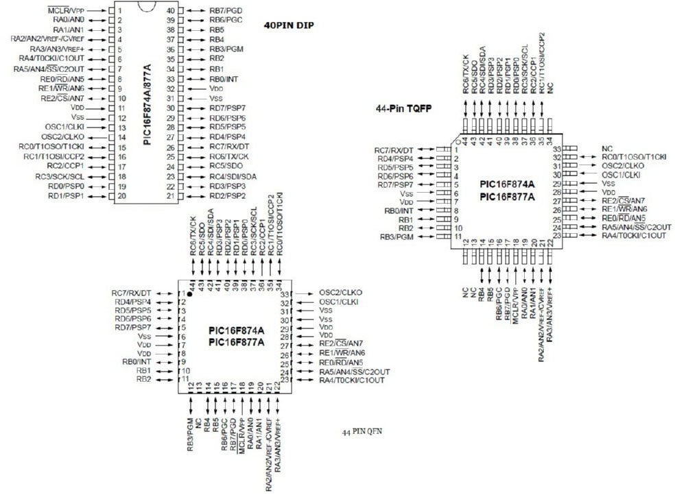
(Pin Diagrams of PIC 16877 Chip)
SOURCE; Microchip Datasheetspdf.com

4. Introduction to the Input/Output port Descriptions
Each port of the microcontroller is associated with two registers. For example, Port C; its registers are PORTC and TRISC. The TRISC register determines whether the port is output or input. Also, you can assign values to each pin independently.
When programming microcontrollers, use compilers for your software work. The best compiler for PIC16877A is MPLAB XC8 COMPILER.
– PORT A configuration functions as an analog input port, digital I/O, or PWM output. Port A has six pins that are from pin #2 to #7; Labelled as RA0 to RA5
– PORT B configuration functions as digital input, analog input, timer input capture, timer output compare, PWM input. Port B has 8 pins, i.e., from pin #33 to #40; Labelled as RBO to RB7
– PORT C configuration is a counter/timer module (input or output), UART, and SPI. Port C has 8 pins also. The first 4 are from pin #15 to #18, and the other 4 are from pin #23-#26. These pins are RCO to RC7
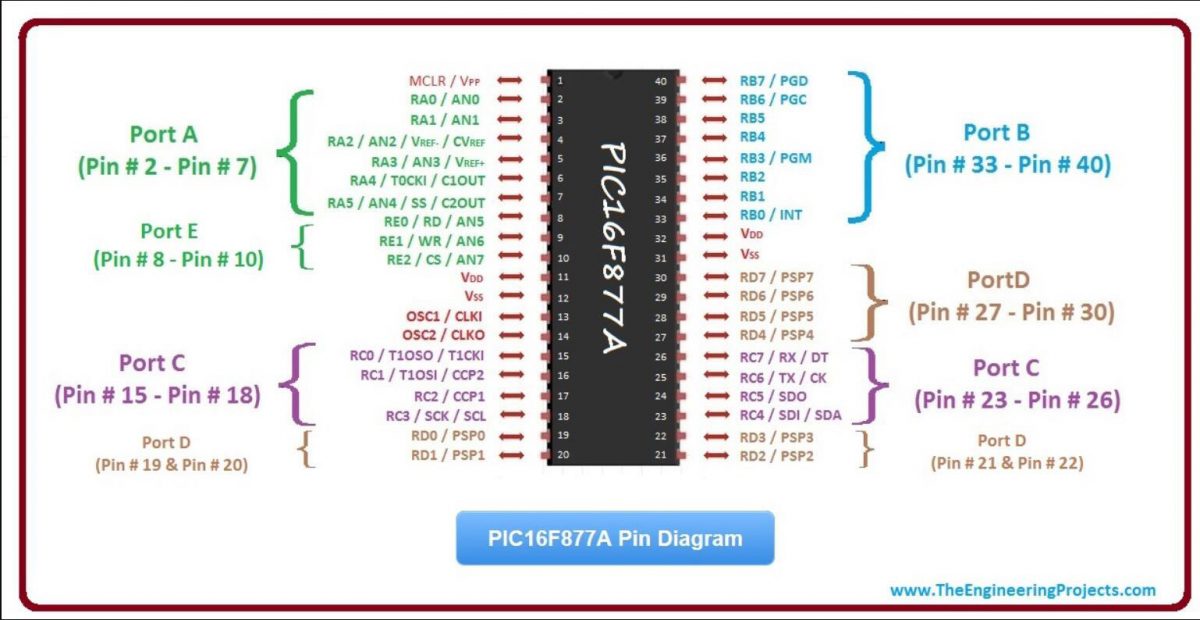
(PIC16F877A Ports Illustrations)
SOURCE: Theengineeringprojects.com
– PORT D configurations are digital input pins, analog input, and timer output. Port D has 8 pins as well. The first 4 are from pin #19-#22, and the others are from pin #27-#30. These pins are RD0 to RD7
– PORT E is for factory use reservation. It has three pins #8-#10, which are RE0 to RE2.
– VDD and VSS are power supply pins, while MCLR is the master clear pin.
– PIC16F877A has up to 18 GPIO pins that allow the controller configuration as input or output using the associated registers.
– In addition to the GPIO pins, there are some other dedicated pins of PIC16F877A on its top surface.
– VDD is the positive supply voltage pin, while VSS is the ground reference.
– PIC16F877A has 23 I/O pins, divided into two banks; bank A and bank B.
– Each I/O pin has a unique bit that can function as input or output when assigned.
5. From theory to Practice- Flashing LEDs using PIC16F877A
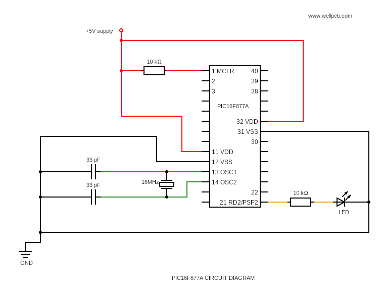
(PIC16F877A Circuit Diagram)
The above diagram shows you how to connect LEDs with PIC16F877A. Also, it highlights the critical microcontroller pins you will need during connection. For quick connection;
- First, connect 5v to MSLR pin#1 and add a 10k Ohm resistor to it.
- Also, connect the 5v to pin #11(VDD). On the other side, attach 5v to pin #32(VSS).
- Provide ground at VSS(pin#12). Then, connect pins #13(OSC1) and #14(OSC2) to the 16MHz crystal oscillator.
- After, connect 2 capacitors of 33pF to the ground. Now, connect pin #31(VSS) to the ground.
- Finally, connect LED and 10k Ohm resistor to pin #21(RD2) to enable program upload.

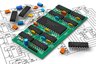
(Electronic Components)
To flash LEDs using PIC16F877A, connect the LEDs between PORTD and the ground. Since we only need to flash one LED, we can combine it with a 10k Ohm resistor. We need to configure PORT-D as output by setting it to high-to-low transition using the output latch to light up the LED.
We can set PORT-D to low-to-high transition by writing 0x01 to the Data Direction Register (DDRB). To set PORT-D to high, we need to write 0x00 to the DDRB register, and this will cause the LED to turn on.
Summary
In this article, we’ve learned about PIC 16F877, its features, and the input/output port of PIC16F877A. We hope you enjoyed it!
If you are interested in the PIC microcontroller, you can also read our other articles. Moreover, if you have any questions about PIC16F877, feel free to contact us.


