A simple short-range FM transmitter that will broadcast within a short range is a good idea for your college or DIY electronics project. In this article, we’ll explicitly show how to make a transmitter for a miniature radio station via simple components.
Contents
Step 1: Gather the Parts
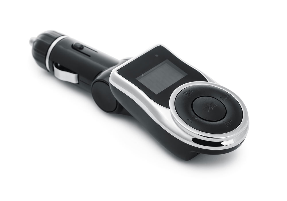
Fig 1: Car mp3 player with FM transmitter
First, you need to assemble the requisite parts for this project which include the following:
Tools
- Soldering gun
- A pair of pliers
- Hot Glue Gun
Electronic Components
- A Copper Clad PCB
- ¼” Bolt
- A 9v battery
- A battery holder
- An Electret Microphone
- A # 18 solid gauge wire
- Two 2N3904 General NPN Transistors
- Two 100nF Ceramic Capacitors
- A 10nF Ceramic Capacitor and 4pF Ceramic Capacitor
- A 40pF Trimmer Capacitor
- Three 10K Ohm ¼w Resistors
- 1K Ohm, 100 Ohm,1M Ohm, and 100K Ohm ¼w Resistors
Step 2: Prepare the Circuit Diagram
Here’s the overall transmitter design.

Fig 2: Circuit Setup
Step 3: Making PCB

Fig 3: PCB Chemical Etching
You need to prepare the PCB through the following key steps:
- First, scrub the copper clad via a scrubber to eliminate dust and other surface deposits.
- Next, using the above transmitter circuit diagram, make a block diagram sketch on the copper clad via a permanent marker. Alternatively, you can iron a glossy paper with a printout on the copper clad.
- Then, make a ferric chloride mixture by adding water to it and mixing thoroughly. Now put the copper clad into the mixture to dissolve unwanted copper.
- Once the etching is complete, remove the copper clad and clean it in water. Wipe it with a clean, dry cloth and make holes in the PCB.
Step 4: Construct the Coil
Make turns of a 19 AWG enameled copper wire on a machine screw. In our case, we’ll be using an 18-gauge wire. Hence, make four to five turns to create an inductor. Also, bend the two legs of the wire coil and ensure they measure about 1″.
Notably, the legs’ mounting holes will be about 12mm apart; hence ensure that this is your inductor’s length. Once done, solder the inductor to the transmitter circuit.

Step 5: Adding the Antenna
You can use a hook-up wire as a radio antenna for this project. Ideally, the radio antenna should measure 5 to 8 inches. Hence, solder a wire on the antenna terminal, as illustrated in the transmitter circuit diagram.
Also, you can install a 3.5mm female audio jack on the audio input ends at this step. It’ll be handy in facilitating the use of plugin mic and audio devices to the transmitter. In addition, The input signal from a device such as an MP3 player will enter via this end.
Step 6: Final Assembly
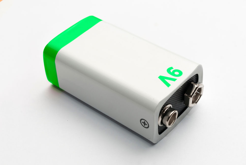
Fig 4: 9V Battery
Attach all the parts as directed by the circuit diagram we covered earlier. Also, if you want to enclose the jack in a casing, ensure you use a washer for a tight grip. Next, connect a 9V power supply battery.
Besides you may also put a power switch between the PCB board and the battery for better control.
Step 7: Tune the Transmitter
You’ll have to be patient during the transmitter’s frequency modulation exercise, as it’s time-consuming. Slowly vary the variable capacitor to change the transmission frequency until you get a zone with a slight distortion.
Then, tune slowly to get more precise radio signals. Once you match the radio receiver and transmitter frequencies, you’ll obtain a clear output from your radio transmitter system. Hence, tune till you have the best audio signal strength.
Conclusion
That’s all regarding how to make a simple transmitter for educational purposes. Don’t hesitate to contact us for further enlightenment; we’ll come to your aid immediately.


