NPN and PNP transistors commonly form part of the Bipolar Junction Transistor. Generally, electronic devices contain transistors whose function is not limited to amplification, voltage stabilizing, detection, rectification, to mention a few. And so, it’s only fair if there are several transistors to perform the operations. This post will focus on a particular NPN transistor known as a TIP120 transistor operating on the amplification mode.
Contents
What is TIP120?
A TIP120 transistor is an NPN Darlington Power Transistor suitable for medium power switching and general-purpose amplification applications in electronic circuits. Its basic parts include a collector, emitter, and base. In addition, it functions to drive high-power gadgets, drive motors and turn on lights. Often, you will find it paired with two transistors in a way that if one transistor amplifies a current, the next transistor will further amplify it.
high power transistor on A Darlington scheme
Precaution on using a TIP120
If you wish to increase the longevity of the TIP120 transistor, be cautious of the following;
- First and foremost, do not operate a load that’s more than 5A or 60V when using the tip120 transistor circuit.
- Then, store the transistor in temperatures not less than -65°C and not more than +150°C.
- Also, use a reliable heatsink and base resistor with the transistor.
Tips on using TIP120 Transistor
Here are a few tips you might consider when using the TIP120 transistor;
- They can replace the regular transistor when it has less power to meet the project’s requirement.
- Second, when you apply a voltage at the base side, you will get a bias which ultimately draws in a small current to regulate the large current at the emitter or controller.
- Then, due to being built by incorporating a planar technology before adding it to the monolithic Darlington configuration, the tip120 transistor now has a low saturation voltage and a high gain performance.
- Fourthly, a small current from a sensor or microcontroller can contribute to a high gain current.
Unfortunately, the excess voltage during high current gain dispels a lot of heat that can burn the components of the transistor. To combat this, always use a good-quality heatsink to regulate the heat dissipation and prevent the circuit from burning.
- Last but not least, tip120 transistor is a current-controlled, unliked MOSFET that has a voltage control.
TIP120 Pin Arrangement and Configuration
The pin configuration of a TIP120 comprises three pins. They include;
A base pin: functions to switch the transistor ON and OFF. In turn, you get to control the biasing of the transistor.
Collector pin: It has a connection to the LED and allows free current flow through it.
The emitter pin is connected to the ground and functions to drain the current passed from the collector pin.
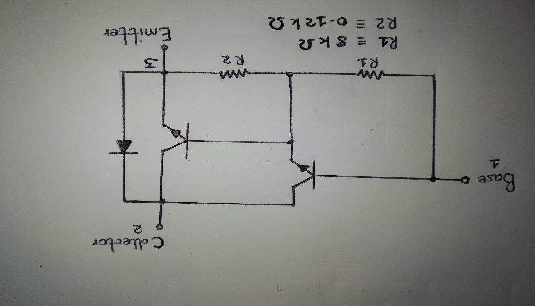
The pin arrangement of a TIP120 (internal circuit schematic)
From the diagram above, you can notice that the TO-220 package contains two transistors. One transistor connects to the second transistor at its base. Then, both transistors will have their collectors connecting and forming a Darlington pair. Gradually, the connection augments the current rating plus the current gain of the transistor in question.

TIP120 Main Features and Specifications
Some of the specifications include;
| @Ic | 500 |
| Vce (maximum) | 60 |
| Ic (mA) | 5 |
| Pd (mW) | 65 |
| Hfe (minimum) | 1000 |
| Vcb | 60 |
In general, the specifications fall under the category of stress ratings. Stress ratings are not to go beyond the absolute maximum ratings. Otherwise, the circuit will get damaged in the long run.
As for the features, they comprise the following components which make up the circuit diagram;
- Max emitter-base voltage (VBE) at 5V
- Then, a high DC gain (Hfe) of 1000 with a 3v, 3A – both maximum and minimum
- The collector-emitter voltage at 60V (VCE)
- 250C Case temperature/ max heat dissipation at 65 W
- Operating temperature alongside the maximum storage – (-65 to +150 °C)
- The material of the transistor – Si
- Collector voltage (VCB) at 60V
- The base current (IB) is at 120mA
- Peak load – current of 8A
- A 5 Amperes continuous collector current
- The collector current capability IC/ current rating is at 5A
- The designated type – TIP120
- The polarity/ type of transistor is NPN
- The complementary silicon transistor is of medium power
Is TIP120 NPN or PNP?
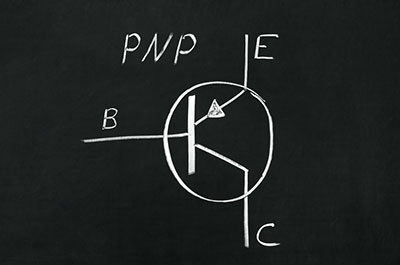
A TIP120 is an NPN. To expound on this, the charge carriers in the tip120 transistor are electrons, much like it is in all NPN transistors. On the other hand, For PNP transistors, the charge carriers are holes.
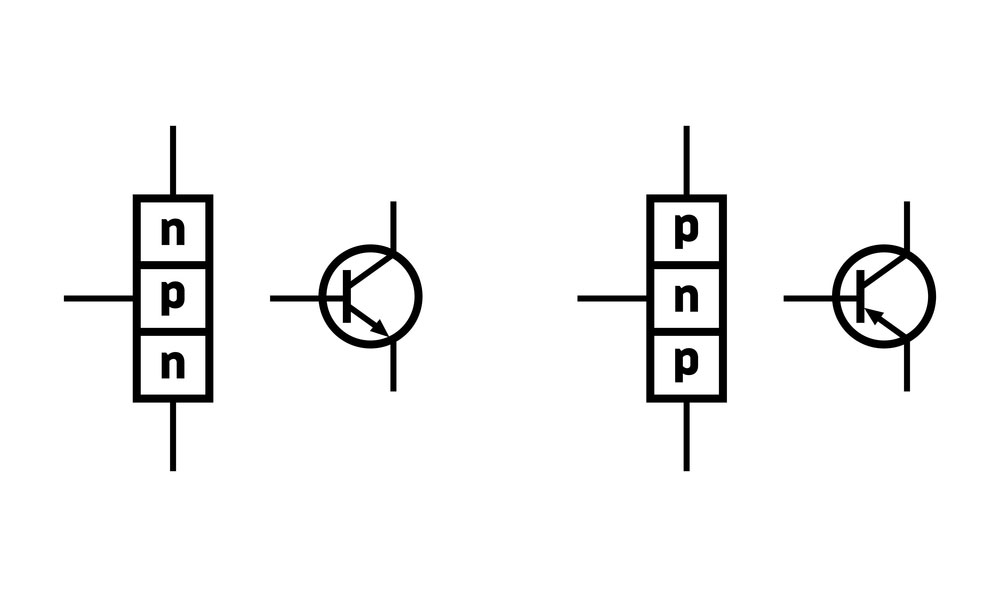
the difference between a PNP and NPN transistor
If you may need to use TIP120 transistor equivalents, then you can alternatively choose from the list we have provided here;
TIP100, TIP107, TIP125, TIP102, TIP110, TIP106, TIP105, TIP101, BDW2, BDT63, KSD560, KSB601, 2N6532, 2SD1415, TIP127 (PNP), and 2SD2495.
Where Can we use Tip 120 Transistors?
We can settle for the TIP120 transistors in several applications such as;
- First, in general-purpose amplifiers/ audio preamplifiers.
- Then, in Darlington transistor devices.
- Additionally, it is applicable in rectifier circuits and inverters.
- In control of motor applications.
- Again, you can use it in microcontrollers.
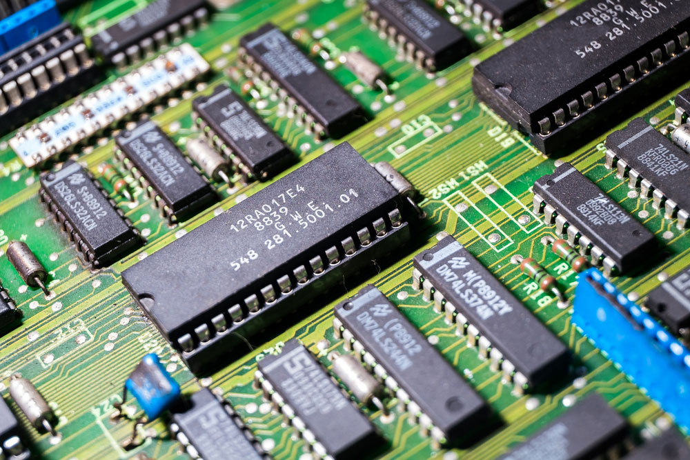
the transistor of LCD TV PCB.
- Also, you will find them in low speeding switches (up to 5A).
Summary
In conclusion, if you need a transistor that can sustain control loads with high current, then the tip120 transistor will be ideal. What’s more, tip120 can easily be in control by a logic device to accelerate to a peak current and switch higher heavy loads of power. Further, some quality features it possesses include but are not limited to an emitter-base voltage of 5V and a load pick up of 5A.
Regardless of the knowledge we have shared in this post; we still have room for questions, inquiries, or clarifications. Hence, we will use the best of our expertise to help when you reach out to us.


