Contents
What is Automated Optical Inspection (AOI)?
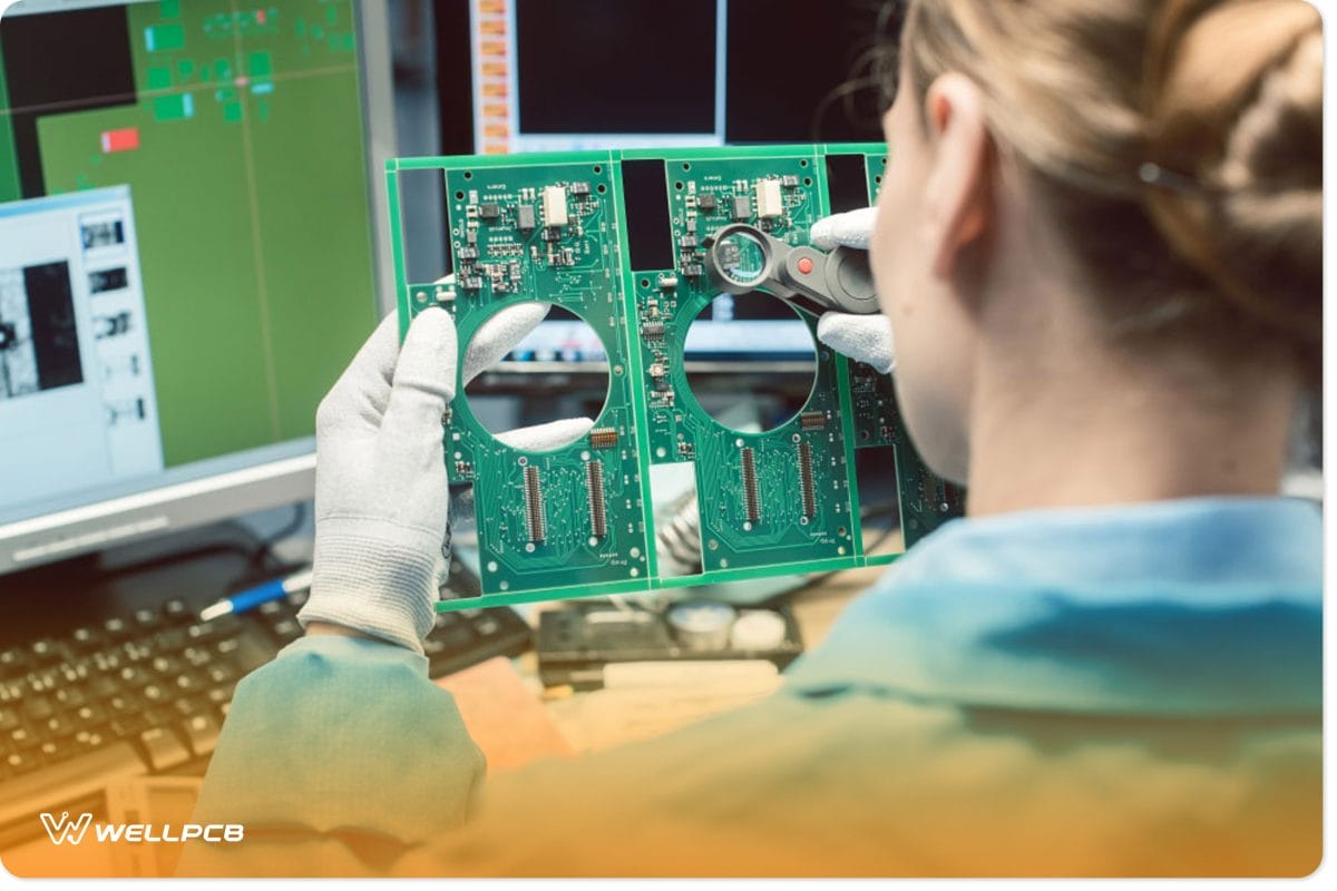
Fig 1: Optical quality control and assembly inspection of an electronic product in the factory
Automated optical inspection, or AOI, is a visual assessment of complete printed circuit boards during fabrication. The inspection relies on a machine scanner that employs light imaging to assess PCB qualities and verify that they’re fit for sale or use.
Working Principle of AOI Test
An AOI machine captures images through LED, UV/IR, or fluorescent lights. I then compare the image to pre-programmed data and put it in the AOI processing system’s memory. The system may terminate production if the difference or Normalized cross-correlation is larger than the tolerance level.
Types of Failures AOI Can Check for
Soldering Defects
AOI can detect Open circuits, solder bridges, solder shorts, insufficient solder, and excess solder.
AOI cannot detect Solder voids and solder quality.
Component Defects
AOI can detect: Lifted lead, missing components, and misaligned or misplaced components.
AOI cannot detect Incorrect component values and faulty component defects.
BGA and CSP Defects
AOI cannot check for BGA shorts and open circuit connections.
Types of cameras for AOI Test

Fig 2: A worker supervises the visual inspection of the AOI of a printed circuit board
There are several image-capturing system variations depending on the specific application and the complexity/expense of the AOI system.
Streaming Video
AOI cameras capture streaming video and retrieve complete frames from it. T e captured frame then produces a still picture on which it performs signal processing. H wever, the streaming video method is not as precise as the other systems but is much faster.
Still Image Camera System
This system requires good lighting, and you should place it close to the target.
Type of Lighting Systems Used for AOI Test
Fluorescent Lighting
However, a significant issue with fluorescent lighting for AOI systems is that the light sources deteriorate with time. Then means that the AOI system will be susceptible to ever-changing quality and intensity of light.
LED Lighting
LED lighting is preferable as they’re more durable and offer a stable form of lighting. L Ds also allows you to control the level and intensity of lighting to match the application. C consequently, they’re preferable to incandescent or fluorescent lighting.
Infra-red or Ultraviolet
PCB companies use IR or UV lighting to enhance or reveal certain defects that are hard to detect.
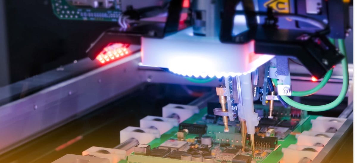
Methods We Can Use to Program an AOI System
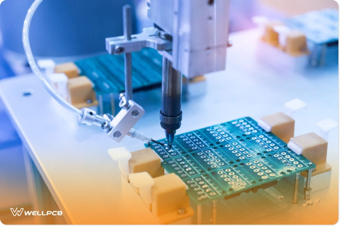
Fig 3: Soldering iron tips of automated manufacturing soldering and assembly PCB board
Use of “Golden Board”
One approach is to utilize a known good board or “golden board” as a reference for the AOI system. T is board is fed into the system to study the necessary qualities. I will examine the components and solder profiles of each junction. Several boards are needed to deliver sufficient variance data to the system.
Algorithm-Based Programming
The system receives PCB data and develops its profile for the board. This approach will likewise necessitate actual boards, albeit fewer are usually required.
How Does AOI Compare With Other Inspection Methods?
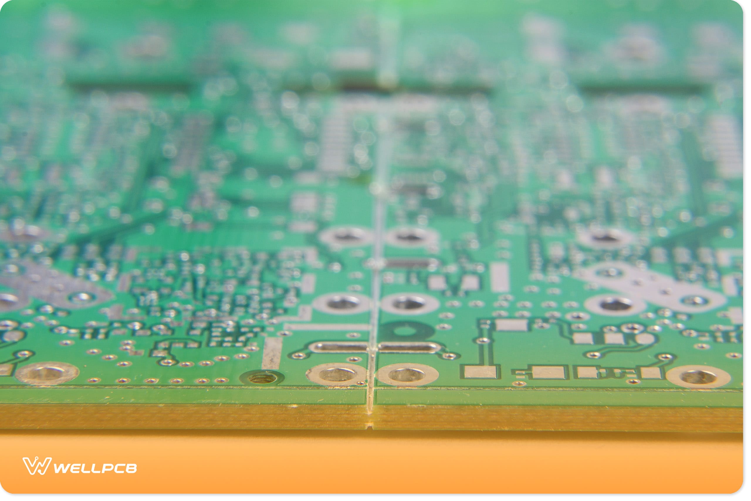
Fig 4: Printed circuit board in a laser machine
Automated X-ray Inspection (AXI)
AXI uses X-rays during inspection instead of light imaging and is popular in evaluating densely constructed or complex design boards. Unlike light imaging, X-rays penetrate through materials to capture imaging accurately. The only downside of the AXI technology is that it’s costly. M st companies only buy it for imaging specialized and complicated boards.
Automatic Laser Test (ALT) Measurement
The ALT uses lasers to measure and scan printed circuit boards. The ALT system uses the lasers’ positions to identify the placement and height of individual components. I analyze reflectivity as the light bounces off the PCB components. T e ALT system may compare empirical measurements to a schematic or specifications.
In-Circuit Testing (ICT)
ICT relies on an electrical probe to check the functioning of an assembled PCB. The electric probe’s working principle is simple. I generate an electric current through the board, informing you of each component’s placement.
Next, it tests for short and open circuits and assesses important PCB qualities like resistance and capacitance.
Manual Visual Inspection (MVI)
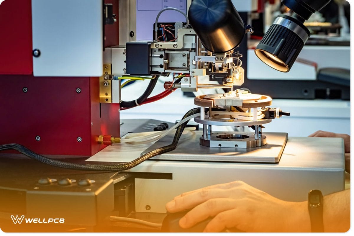
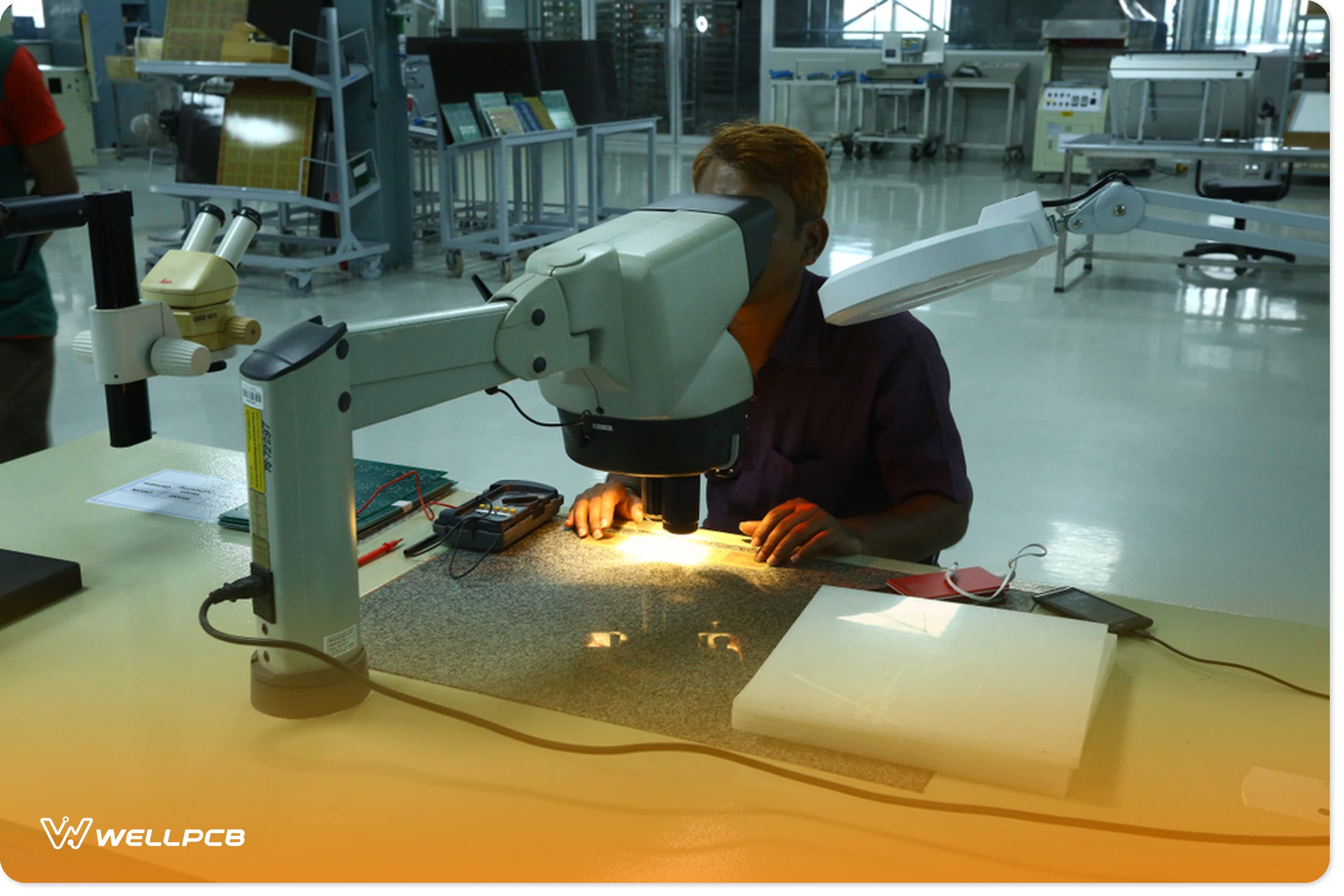
Fig 5: Manually inspecting PCBs under a microscope
From the name, MVI is when a human inspector studies the board for defects. Most PCB companies use the MVI method as a last resort, as human handling may introduce board defects.
Conclusion
In conclusion, you must conduct regular inspections in all PCB manufacturing areas to reduce the number of errors and defects. It’s only in this way that you can correct production errors that may spread to other boards.
As boards are getting more complex, we can no longer rely on manual inspection only but incorporate AOI tests. Contact us for more information or to procure the AOI test technology.