Contents
Functions and Uses of the Audio Delay Circuit
An audio delay line is a fundamental concept that transforms the delayed music from an analog signal to a digital signal. It is then put into a shift register or any digital delay or storage medium. A digital-to-analog converter converts the delayed digital signal into delayed audio.
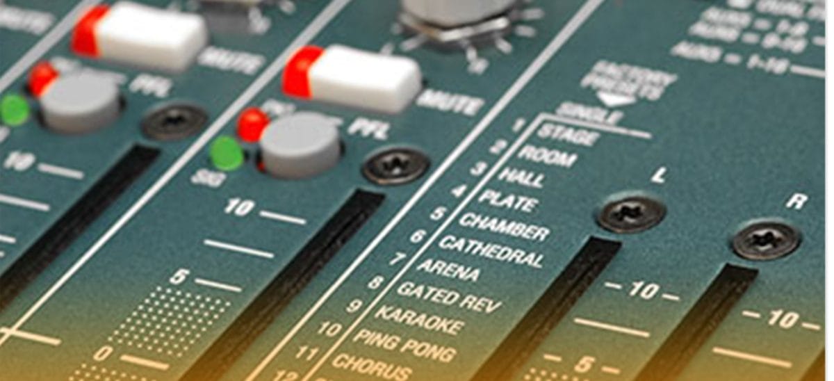
This circuit helps achieve a great audio experience. This power amplifier generates an echo (audio signal time delay) and reverberation. Yet, the design of a space or room determines the listening experience for the music played in that space. For instance, if a room has several glass windows, it has an excessive echo effect on the music. Meanwhile, the music loses every echo and reverb effect if many things fill up the room. This kind of room produces a dull and bland sound. So, the audio delay circuit aids in the restoration of the mood created by the music. It is better because you don’t have to worry about what interior design you choose.
It was challenging to get an audio signal delay circuit back in the day because the required devices were costly. New technology makes the circuit’s construction cheaper, and this innovation is the Bucket-Brigade.
First, we fix an audio signal into the bucket-brigade design input. Then, we make the ICs work with a clock generator; the audio input signal moves in a stepped manner until it reaches the output audio with the desired delay. So, we achieve a reverberation effect when the delayed signal recirculates into the original signal.
Audio Delay Circuit Operating Principle
The bucket-brigade ICs are the essential parts of the circuit. Also, there are no pricey analog-to-digital and digital-to-analog converters in the courses. There is a phasor/flanger mode in the audio delay circuit. The audio’s frequency, whose wavelengths are like the time delay, will die in this setting. But all other frequencies get stronger. Then, a comb filter with a frequency range between the notches adjusts by changing the clock frequency. The phasor/flanger mode also helps create stereophonic signals from monophonic signals, and one channel receives the phased output by injecting the delayed signal. Then, the other gets the result obtained by removing the delayed signal.
A low-pass filter (anti-aliasing filter) cleans up the output waveform and other duplicate signals. The signals existed at the input but got delayed by 256 times the clock frequency range. For example, when the clock frequency is 100 kHz, the maximum delay is 256 x 1/100,000 = 2.56 milliseconds. The clock rate influences the sampling rate of the music signal on the input. Thus, a 50% lower clock frequency is the most significant audio frequency it conveys. As said earlier, the bucket brigade makes the circuit’s construction cheaper. Next, we discuss the Bucket-Brigade and the all-pass filter.
Bucket Brigade
Bucket Brigade Devices are chips with several capacitors, and they are responsible for the delay of audio signals. The name is from a historic firefighting practice where people shared buckets of water in a line. The bucket-brigade analog shift register works like the bucket-brigade digital shift register. Hence, the name.
Capacitors represent “buckets” connected to the PMOS IC in shift registers. Over 1000 capacitors of a single capacitor and some MOS transistors per stage on a single chip. The elements transmitted from one step to the next are packets of electrical charge. We all know how difficult it is to pour water into and out of a bucket simultaneously. Moreover, charging and discharging a capacitor at the same time is difficult. The shift registers and a pair of out-of-phase clock frequencies overcome this problem. The buckets with “odd” numerals merge with “even” figures in the following buckets. It happens during the period when the first clock is high. As soon as the second high clock strikes, the even buckets toss into the odd buckets that follow.
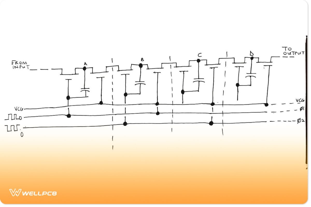
Bucket Brigade Device
All-Pass Filters
This design allows all frequency components of the input signal to pass through. It does this without attenuating. Any wire works for this function. But, the unique feature of an all-pass filter is that it offers predictable phase changes. It does this at different frequencies of the input signal.
People use these filters in the field of communications technology. The transmission of signals across long distances across transmission lines results in a shift in their phase. These transmission lines include telephone wires. We use all-pass filters to correct these phase shifts. They refer to them as delay equalizers or phase correctors in some circles. Despite that this filter has a significant response of one, it offers a phase shift. All-pass filters customize the delay responses of elements in your signal-processing chain.
The group delay specification needs you to use an all-pass filter in cascade with your filter. Also, audio circuits use all-pass filters to end undesirable phase shifts, resulting in the generation of unwanted background noise. Furthermore, people use them in the electronic communication system to compensate for phase shifts in voice signals.
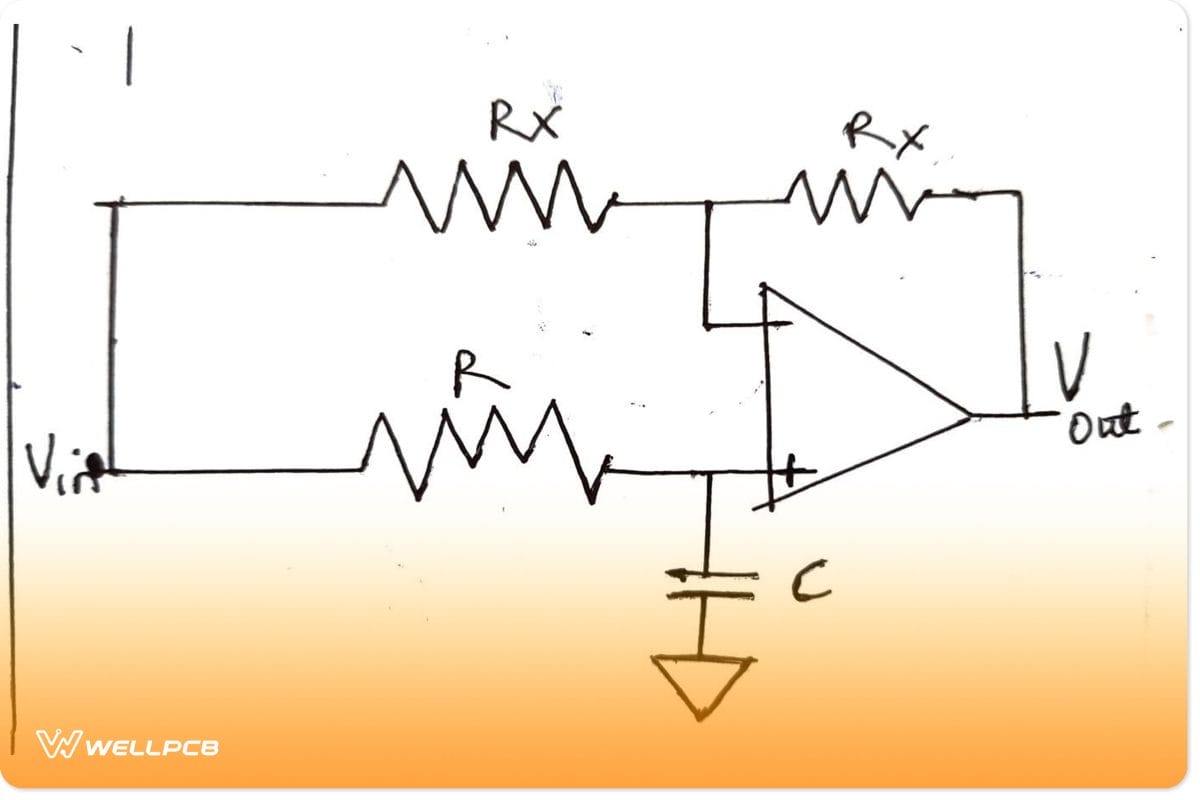
All-Pass Filters
The Construction of an Audio Delay Circuit
The diagram below explains the resistance values used in the construction of an audio delay circuit. Also, let us look into the critical factors to consider while constructing an audio delay circuit.
- Suitable Resistance Value: While constructing an audio delay circuit, using the right resistance value is essential. It helps in determining how long the transistor remains switched on after releasing the push button.
- Suitable Materials: The necessary components used in the simple circuit’s construction are transistors, electrolytic capacitors, and diodes. The capacitor value decides how long the transistor stays conducting. Also, putting one transistor in the circuit induces time delays of only a few seconds. However, adding one more transistor increases the circuit’s sensitivity.
- Power Supply Selection: A voltage regulator, IC6, generates the primary 15-volt supply. The shift register has +1 and +20 volt sources from R22, and R23 is the +20 volt rail. The 10.5-volt voltage line is necessary since a single-ended supply drives the op-amps.
- Capacitor Pin Direction: Insert all semiconductors and electrolytic capacitors with care. It would help if you placed them in the right direction. The MOS devices are sensitive to static charges, and the static charge created on your fingers destroys them. You can either put the ICs on the PCB or use IC sockets.
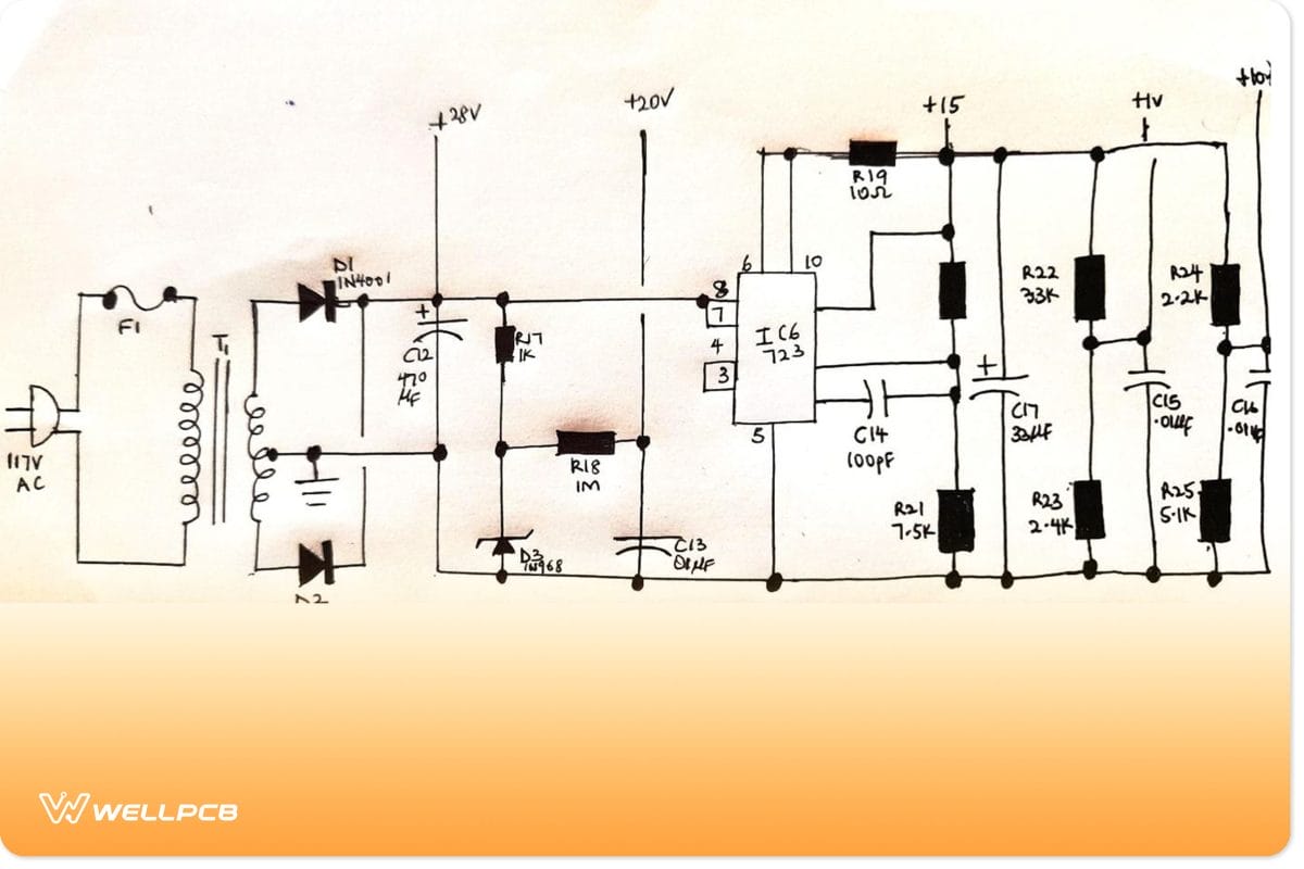
Power Supply of an Audio Delay Circuit
Conclusion
An audio delay circuit is essential because it makes music or sounds more attractive in a room or given space. The Bucket Brigade device has completed the construction of this circuit cheaper. So you don’t have to worry about the cost.
However, while constructing an audio delay circuit, you need to be careful in inserting the materials in the right places. Make sure to handle them with utmost care. Now, you can create more prosperous and fuller sounds. Kindly contact us if you have any questions.


