Contents
What is a Clap Switch?
A clap switch does precisely what the name suggests, and it’s a circuit that turns on any light or any other electrical appliance connected to it when you clap or make a sound on the same pitch as a clap.

Clap Sound
Also, the clap switch’s most crucial component is a sound sensor (condenser mic), which converts good energy into electrical pulses, which help generate the input you want.
Here are some fun facts about the clap switch.
The innovative circuit was created by E Dale Reamer, R Carlie, and Stevens, and its primary purpose was to help people with mobility issues easily control electrical appliances.
The electrical appliances you can control with clapping action include tube lights, fans, bulbs, and many more.
Working Principle
A clap switch is a circuit that works through clap sounds or sounds on the same frequency. Some clap switches require you to clap twice, while some require you to clap once to turn on/off. However, it depends on the circuit’s design.
The clap switch works on a basic concept of sound. Thus, the microphone in a clap switch receives the clap sound you generate and makes a small electrical signal that’s powerful enough to control electrical appliances.
Advantages of Clap Switch Circuits
- It’s an energy-efficient system and not expensive
- High reliability & High accuracy
- It doesn’t require any form of man-power
- The main advantage is to control any electric device connected to it like light—from anywhere in a room by clapping action.
Disadvantages of Clap Switch Circuits
- Sometimes, it’s easier to use a regular light switch
- You may experience intrusions when using this circuit in buildings
- The major disadvantage is the filter you must add for the circuit to work properly
Clap Switch Applications
The clap switch isn’t just for switching lights ON/OFF. You can also use them to control different electrical appliances like:
- Fans

Fan
- Radios

Radio
- Tube lights

Tube lights
- Motors
Motor
- Television

TV
- Air conditioner

Air Conditioner
- And any other basic circuit you want to control via sound
How to Build a Clap Switch Circuit
Here, we’ll look at building an easy clap switch circuit diagram using the 555 timer IC. Here’s the circuit diagram we’ll be working with:
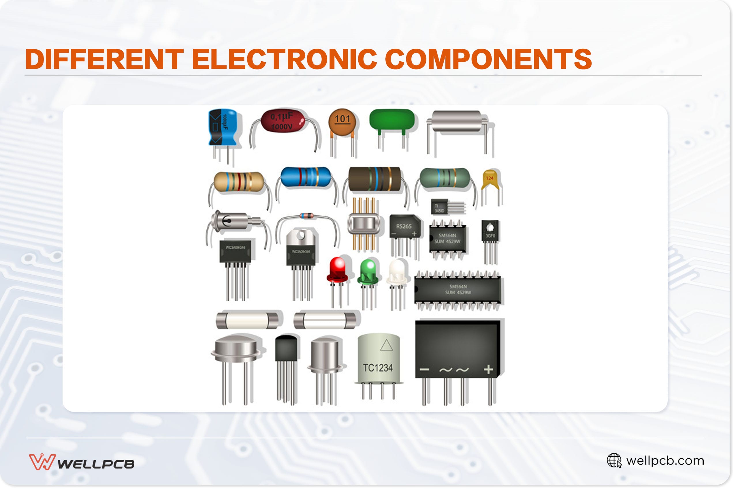
Required Components
Here are the components you need for this circuit:
- LED (1)
- 555 Timer (1)
- Resistors (1k, 470 ohms, and 56k ohm)
- 10 uf capacitors (1)
- Condenser Mic (1)
- BC547 transistors (2)
- 9V battery power supply (1)
Steps
Now, let’s look at the steps you need to follow to build this circuit:
Step 1: Connect the Pins of the 555 IC
First, take a piece of jumper wire and create a connection between pin 4 and pin 8 of the 555 IC.
Step 2: Connect your Components
Connect the positive pin of your 10 capacitor to pins 6 and 7 and the negative pin to pin 1 of the IC.
Next, take your 470 ohms resistor between the positive pin of the capacitor and pin 8 of the IC.
Now, you can connect the emitter pin of your transistors to pin 1 and the collect pin to pin 2 of the 555 timer IC.
Also, solder your 1K resistor between the IC’s pins 2 and 4 and connect your 56K resistor between the transistor’s base pin and the IC’s pin 4.
Step 4: Connect your Components 2
Take your LED’s positive and negative pins and sell them to pins 3 and 1 of the IC, respectively. Also, solder the +v end –ve pins of the battery clip to pin 4 and pin 1.
Additionally, solder the positive wire of the condenser microphone to the transistor’s base pin and the negative wire to pin 1 of the IC.
Step 5: Test Your Circuit
To test this circuit, connect your 9v battery to the battery clip and make a clapping sound. You should notice the LED connected to the circuit starts to glow once the circuit catches the clap sound.
PCB Layout Tips for Clap Switch

PCB
Here are some tips to help you minimize the chances of having any problems with your PCB layout:
- Think of using mechanical relays: Although the circuit diagram above shows an LED as the electric load, some applications may require a light bulb, fan, or other simple electrical appliances. So, in such situations, you should use a mechanical relay so you can have electrical separations on your PCB.
- Keep components with significant voltage away from the components of the clap switch: route any traces of high voltages away from the clap switch components to avoid significant damage or interference from the relay.
- Make a short condenser mic trace: it requires a low voltage turn on the 555 timer and produces an analog signal. So, to prevent any outside electrical interference or a false trigger, keep the condenser mic’s trace short.
Wrapping Up
Finally, here are a few tips to help you understand the circuit you’ve built or you’re making. The course uses a sound-activated sensor that detects the audio signal (clap sound) as input and generates the load’s output.
Once you connect the battery to the circuit, it immediately activates and makes clap sounds or similar sounds.
Well, that wraps up this article. If you need further assistance or have any questions, feel free to reach us. We’re always happy to help.