All electrical outlets get faulty from time to time. When an electrical device develops a fault, such defects often arise due to a disruption in one of the device’s wires. Without the continuity tester circuit to help you troubleshoot the device’s circuit and find where the break in the wire occurred, faults become even harder to find.
The good news is making a continuity tester circuit on your own is easy with just a few parts. Here, we explain the working principle of a continuity tester circuit, list all the materials you’ll need to make one, and explain the steps in building your own. Let’s get into it!
Contents
What is a Continuity Tester?
A continuity tester circuit is an essential tool in electronics that helps you check for continuity in a circuit and detect faults in it. Some components include a battery in a case, with a test probe connected to one end of the battery case and a test lead with a clip attached to the opposite end. It is similar to a non-contact voltage tester in many ways.
As a rule, the simple continuity tester circuit consists of a cord with either two metal testing probes or a testing probe and an alligator clip, between which it generates a harmless test or auxiliary voltage (usually 1.5 to 4.5 volts) utilizing a built-in battery.
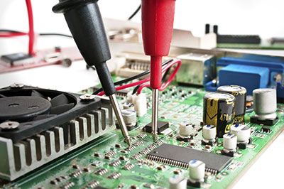
(Test PCB workbench)
Continuity Tester Circuit: The Working Principle
The principle of operation is relatively simple. For a continuity test, we require the two test probes of the measuring device (battery-operated digital multimeter or simple continuity tester), each attached to measuring points such as an outlet slot or the outside of a wire. The purpose of these electrical testers is to probe voltage in both AC and DC circuits.
The internal battery of the measuring instrument generates a harmless auxiliary voltage or accurately measures the voltage in the low volt range. The measuring instrument’s optical and audio signaling devices show positive results when current flows between the measuring points. If the signaling devices do not respond, you will have an imperfect circuit.
Resistance meters serve as continuity testers. Generally, they have a continuity tester function, in which they generate a beep if they fall below a specific resistance value.
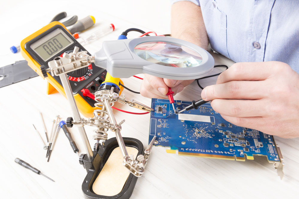
(Technical staff use multimeter for testing)
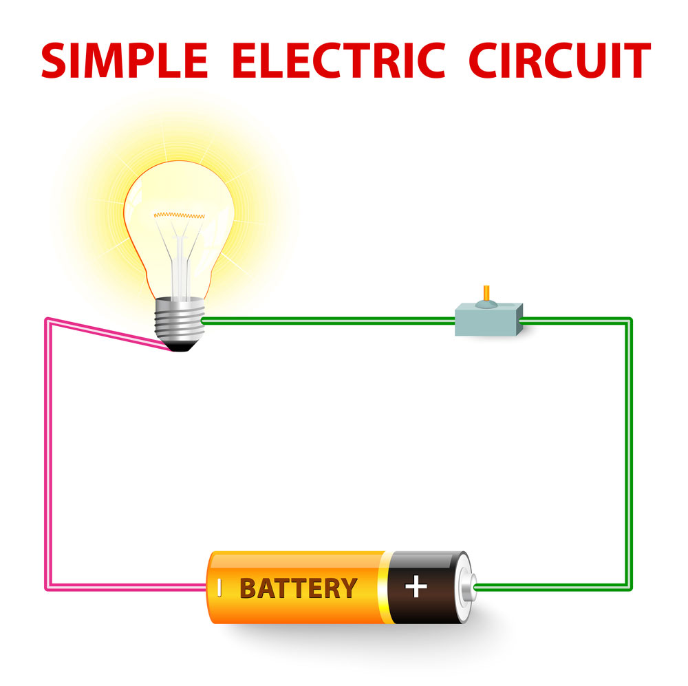
Interpretation of Circuit Diagram
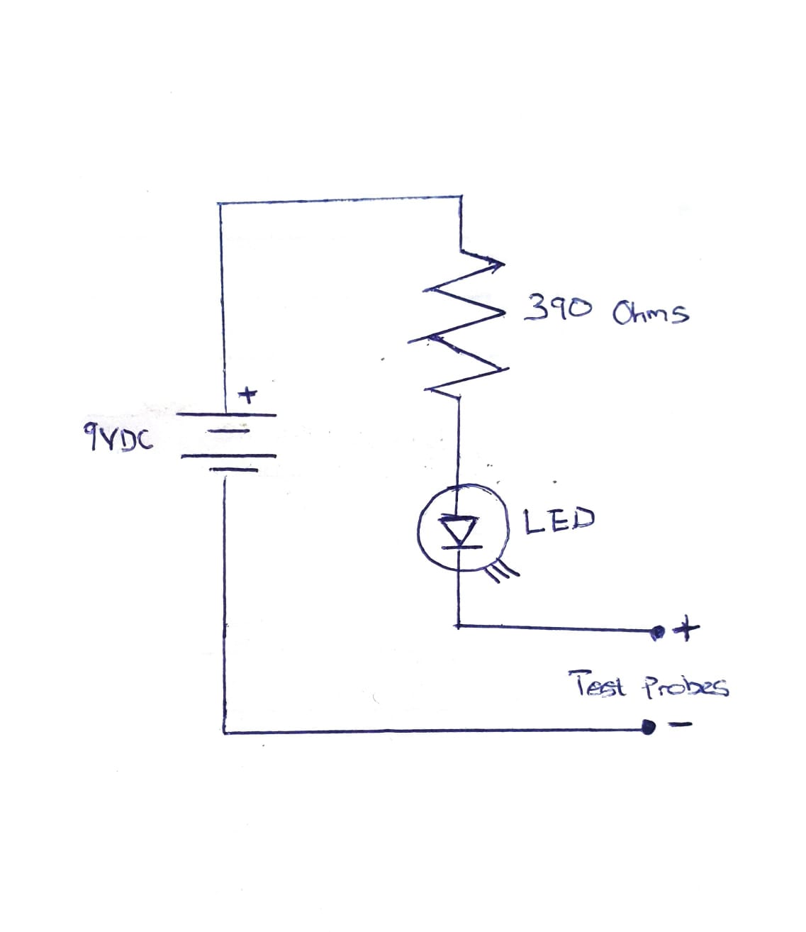
(A Simple Continuity Tester)
How Do You Build a Continuity Tester Circuit?
The basic materials you will need to build a tester are an audible continuity buzzer indicator, an LED lamp, a transistor amplifier, and two sockets. This inexpensive circuit is highly effective in detecting defects in circuits. A junction box, which stays on a wall, encloses the fundamental components.
(A Simple Circuit)
Parts Needed to build a Continuity Tester Circuit.
Here, we’ll be discussing how to build a continuity tester using a LED lamp. Below are the parts we need for the LED continuity tester and the steps in building this tester.
Parts Needed
- LED
- Alligator clip
- Power supply
- 470-ohm resistor.
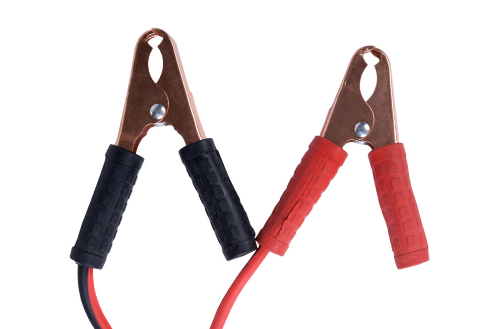
(Alligator clip)
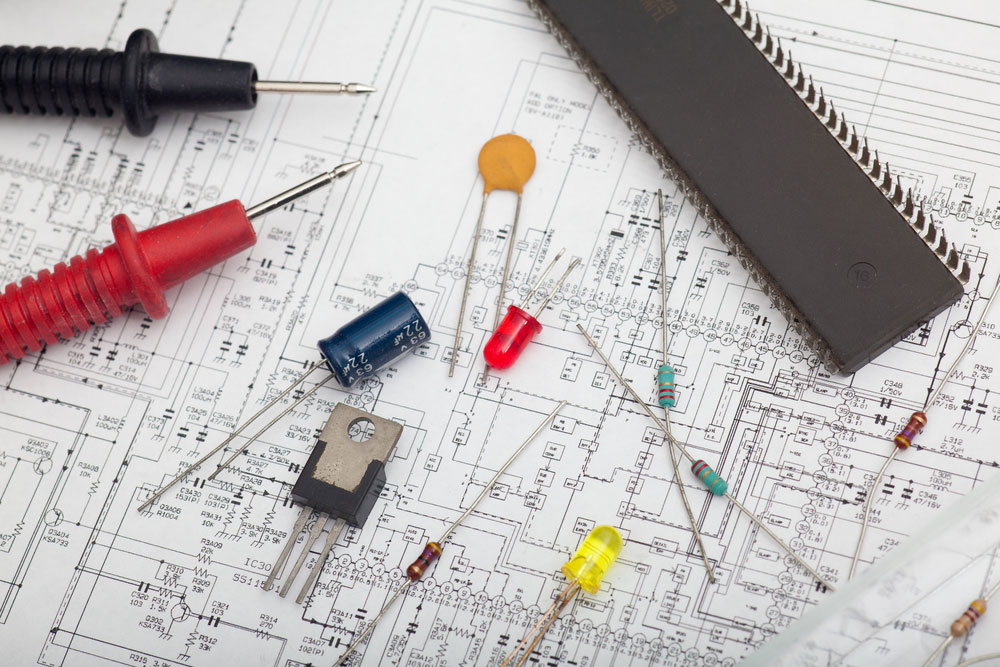
(PCB electronic components)
Steps in Building a LED Continuity Tester Circuit
The LED tester circuit seems like the simplest method to build a tester circuit. Let us go through the steps.
- We need about 3V to 5V to power the circuit.
- Put an alligator wire with the positive voltage line of the power supply.
- Then, skip a part on the breadboard and put another alligator wire there.
- Connect a LED and a 470-ohm resistor in series.
NOTE: The job of the 470Ω resistor is to reduce the current reaching the LED, and it is to ensure that the LED doesn’t blow.
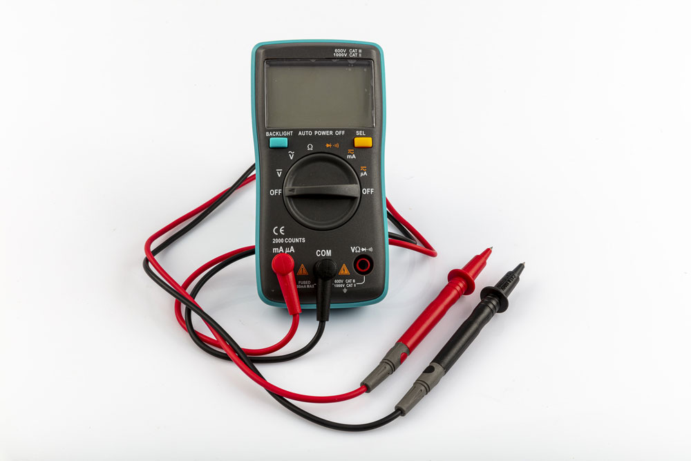
How to Test for Continuity
- Ensure that the circuit you are testing is off.
- Toggle the selector dial to Ω.
- Connect the probes and the test lead on the base terminal.
- To test the conduit, connections, and battery life, touch the sensors/probes together. Depending on the maker, the meter should show I or OL, and it should sound the audible alarm.
- If you’re doing the last test, turn the meter off and store it safely.
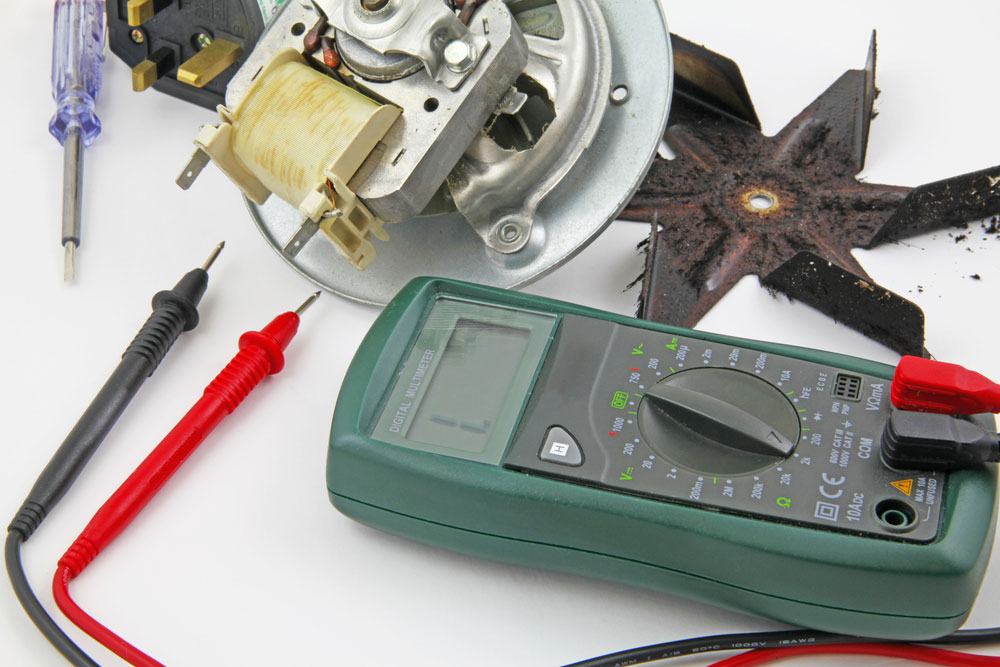
(Testing for Continuity)

Possible Problems During Circuit Construction.
Circuit breaker trips
Sensitive circuits use circuit tripping as a safety precaution. When there’s much load in a circuit, a simple circuit breaker automatically trips off.
To avoid this issue, take the following steps:
- Only connect the necessary appliances.
- Avoid overloading a single circuit.
Instead, disburse your power needs across various circuits. If a specific device leaves the breaker periodically, the device is likely to be defective and needs some checkup.
Ineffective Power Supply
Make sure your power supply provides adequate power to the right places without being overstrained. If the power supply is inadequate, it will cause a voltage drop, reset microcontrollers, or make other components behave erratically.
A continuity tester is a battery-operated device. Thus, it is essential to constantly maintain a healthy battery life to get the most accurate result. When tested under no-load conditions, batteries typically seem to have the proper voltage, but the voltage drop is enough to cause a circuit malfunction when connected to the circuit. Therefore, you must measure the battery voltage under no-load as well as full-load conditions.
(electronic circuit board)
Continuity Tester Circuit Application
A continuity tester finds out the integrity of switches. For instance, a good fuse should have continuity. It also fuses electrical power and conductors, connections, and other components. It is crucial always to switch off the circuit while testing as this may give a false alarm.
One actual application is the continuity test of many wires at their lowest price. It is to find the two ends belonging to one of these wires. It causes resistance between the “right” ends and only between the “right” ends.

(circuit board and engineering equipment)
Conclusion
We use electrical and electronic equipment in a variety of applications that are prone to errors and defects. In most cases, these defects are minor and superficial and take the form of wire breaks, such as a break in a power line.
Since most of this equipment includes many wires, troubleshooting becomes quite cumbersome and challenging to diagnose. Therefore, a tester is one of the essential devices every electrical personnel must own. You can always contact us if you have any questions.


