An ammeter/amp meter (abbreviation for Ampere meter) is a device that you can use to measure current in a circuit. Digital Arduino Ammeter (A) are the units of measurement for current flow, and this is where the ammeter gets its name. Some people may refer to them as current meters.
Arduino microcontroller and microprocessor boards give you access to a large plethora of projects. For instance, you can build your very own ammeter. It’s a great project to undertake because of its reusability. Thus, in the following guide, we’ll show you how to build your very own Arduino Ammeter to measure current.
Contents
How To Build Your Own DIY Arduino Amp Meter
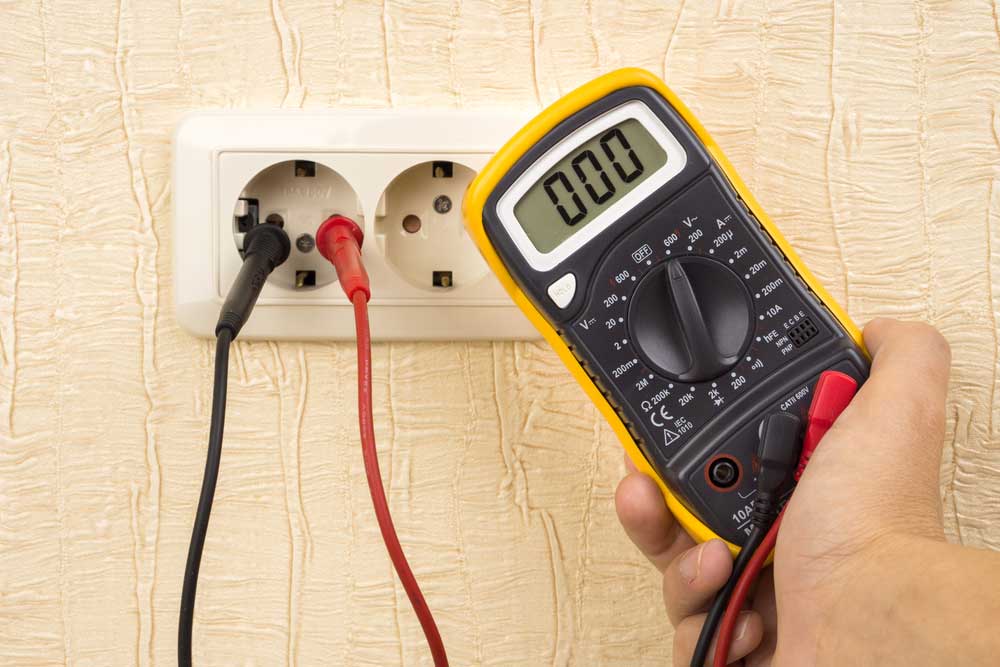
Electricians working on an electric meter
Our goal for this guide was to ensure that it’s easy to follow and uses as few resources as possible. You don’t need to be a seasoned engineer to build the following project.
Required Components:
- Arduino Compatible 128×32 OLED LCD Display

- INA219 Current Sensor Breakout
- Arduino Pro Mini Rev 5 (5 Volt)
- CH340 Programmer
- 9V battery box (with batteries)
- JST PH 2-Pin Cable – Female Connector
- JST Right-Angle Connector
- Mini Small Flathead Screwdriver
- Six-pin right-angle header for Arduino
- Soldering Iron
- 24 SWG Tinned Copper Wire 500g FUSE WIRE 18 AMP 0.56MM
- Mini Pliers
- Wire Cutter
- Adhesive Foam Pad
- 4 Pin Female to Female Jumper Cable
Arduino Amp Meter Hardware Configuration
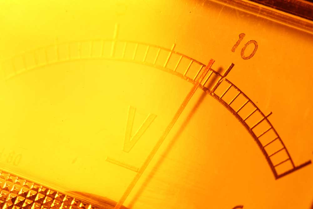
Electric meter
Preparation
Before we begin to assemble our Arduino-based Amp meter, we’ll need to ensure that we have the right equipment and tools. Our Arduino Amp Meter will comprise three main parts. This includes the 128×32 OLED display, which will output current readings. The INA219 current sensor will measure the current or voltage values, while the Arduino Mini will compute, process, and connect everything.
The Arduino Mini contains two rows of pins down the side. We will need to connect the INA219 current sensor using the Arduino Mini’s I2C protocol.
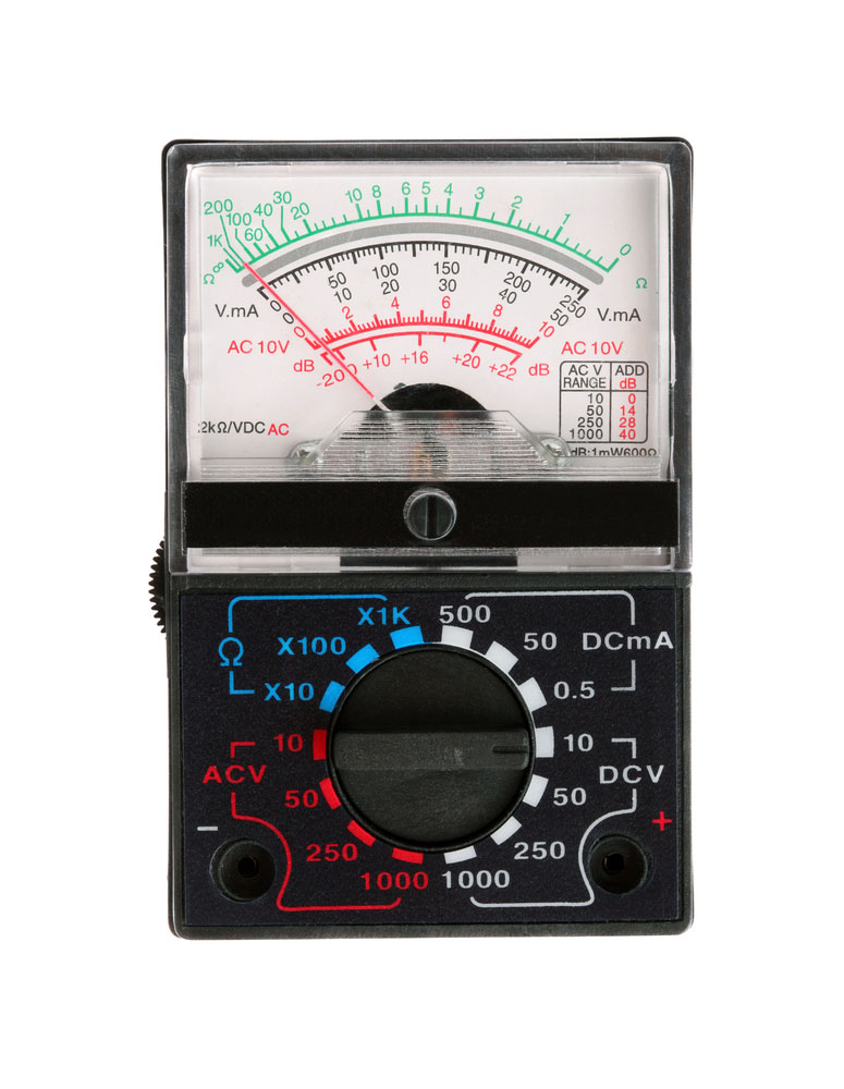
Analog multimeter
Make sure that you’re using An Arduino Mini Pro 328P Rev 5 board or a replica. If you can’t find one, you’ll need to ensure that the version you’re using has an A4 and A5 pin.
You’ll notice that the pins on the Arduino Pro Mini line up with the pins on the INA219 sensor and the OLED display module. This is assuming that you’re using the right hardware.
The VCC and GND pins from the INA219 sensor will connect to the VCC and GND pins on the Arduino Pro Mini. While SDA will connect to the A4 pin and SEL will connect to the A 5 pin. To simplify, it will look something like this:
1. INA219 VCC -> Arduino Pro Mini VCC
2. INA219 GND -> Arduino Pro Mini GND
3. INA219 SDA -> Arduino Pro Mini A4
4. INA219 SEL -> Arduino Pro Mini A5
This will work similarly with the OLED display too:
1. OLED Display VCC -> Arduino Pro Mini VCC
2. OLED Display GND -> Arduino Pro Mini GND
3. OLED Display SDA -> Arduino Pro Mini A4
4. OLED Display SEL -> Arduino Pro Mini A5
Once you’ve ensured that these pins match up and align, we can begin to build our Amp Meter.
Instructions
1. Use your soldering iron/gun to remove the pins from both the INA219 sensor module and OLED display module.
If there is any plastic cap or covering, you’ll need to remove it using a flat head screwdriver
Heat the back of each pin one at a time and shake it off
2. Cut four pieces of 40mm long wire from your SWG tinned copper roll
3. Connect and solder the wires onto the OLED display module, replacing the pins we removed earlier
4. Use the freshly soldered wires from the OLED display module and connect them to the pins on the Arduino Pro Mini.
Align the pins using according to the description we provided in the preparation section
It should look like a sandwich if done correctly
Try to prevent the wires from touching – use your screwdriver to create space between them
5. Solder the wires to the Arduino Pro Mini but don’t cut them short – we’ll need to connect them to the INA219 sensor module
You may shorten the wires on top of the OLED board if you haven’t already
6.Match the pins from the Arduino Pro Mini and connect them to the INA219 sensor module using the wires
Make sure that the wires aren’t touching – you can pry them apart using your screwdriver
Solder the wires to the INA219 Sensor
7.Make sure to cut each wire to neaten up the setup
Connect the right angle six-pin header to the Arduino and solder it on
8. We will need it to upload code to the Arduino
You’ll need to push the OLED display module up to solder the headers – be cautious when you do this
Connect the JST-PH 2 female pin connector to the battery box wires
Connect and solder the JST right-angle connector to the Arduino Pro-Mini
The red wire (live) will connect to the RAW Pin, while the black wire (neutral) will connect to GND – make sure you wire and solder accordingly
Connect the 4-pin female to female jumper cable from the Arduino Pro-mini to the CH340 programmer
Connect the CH340 programmer to your computer’s USB port
Refer to the Software Configuration section of this guide to programming the Arduino Ammeter
Once you’ve done programming the Arduino Pro Mini, you should be able to connect a circuit to the sensor module and get a reading from the OLED display. You can power the entire ammeter using the CH340 programmer through its USB or using the 9V battery pack.
Arduino Amp Meter Software Configuration
You’ll need to program the Arduino Pro Mini and OLED display screen. Before proceeding with the instructions in this section, you’ll need a basic understanding of how programming with the Arduino IDE works for compatible devices. In this section, we’ve included a sketch for each part of our Arduino Pro Mini.
OLED 128×32 Code
1. #include <Arduino.h>
2. #include <U8g2lib.h>
3. #include <SPI.h>
4. #include <Wire.h>
UEG2_SSD1306_128x32_UNIVISION_F_HW_12C ueg2 (USG2_RO);
void setup (void) {
u8g2.begin();
ina219.begin();
}
void loop (void) {
u8g2.clearBuffer(); // clear the internal memory
u8g2.setFont (u8g2_font_logi303032_tr); // choose a suitable font
u8g2.setCursor(0, 32);
u8g2.print(millis());
u8g2.sendBuffer(); // transfer internal memory to the display
delay(200);
}
INA219 Code
1. #include <Wire.h>
2. #include <Adafruit_INA219.h>
Adafruit_INA219 ina219;
void setup (void)
{
uint32_t current Frequency:
Serial.begin(115200);
Serial.println(“Hello!”);
Serial.println(“Measuring voltage and current with INA219 …”);
ina219.begin();
}
void loop (void)
{
1. float shuntvoltage = 0;
2. float busvoltage – 0;
3. float current_mA = 0;
4. float loadvoltage = 0;
shuntvoltage – ina219.getShuntVoltage_mV();
busvoltage = ina219.getBusVoltage_V();
current_mA = ina219.getCurrent_mA();
loadvoltage – busvoltage + (shuntvoltage / 1000);
Serial.print(“Bus Voltage: “);
Serial.print (busvoltage);
Serial.println(“V”);
Serial.print(“Shunt Voltage: “);
Serial.print (shuntvoltage);
Serial.println(” “);
Serial.print(“Load Voltage: “);
Serial.print(loadvoltage);
Serial.println(” “);
Serial.print(“Current: “);
Serial.print(current_mA);
Serial.println(” mA”);
Serial.println(“”):
delay(2000);
}
*Note: You should name the sketch for the INA219 code GetCurrent.

Conclusion
After you’ve configured the hardware and software for this project, you should be able to use the sensor module to measure the current flow from any simple circuit. As you can tell, this is a very simple project. It won’t take you very long to complete. It’s perfect for beginners and hobbyists. Additionally, you can repurpose this project to work as a voltage sensor or just use it as a tool to measure current flow in your other projects. Whatever you decide, we hope that you’ve enjoyed reading the guide. As always, thank you for reading.


