
Are you tired of dealing with remotes that don’t have as much function as you need? Well, a quick fix is to build a DIY remote control.
With this device, you can control many electronic appliances with a DIY remote, including televisions, DVD players, and air conditioners. Although building a remote control is easy, some parts might get tricky if you’re not careful.
But, don’t worry. We’ll teach you how to build different remote control projects with and without microcontrollers.
Ready? Let’s build!
Contents
How can I Make Remote Control From Any Device?

TV Remote App on Android
While you can’t just turn any device into a remote controller, your smartphone is a viable tool. But this device must have IR capabilities.
In other words, your device must have an IR blaster. Otherwise, you won’t be able to send commands from your phone to other devices.
In addition, the IR blaster is not downloadable. Hence, you must check your phone for it and download the IR test app. With this, you’ll know if your device meets the requirements.
You can start by searching the app store for “IR blaster.” Then, go through the list of applications and choose one with a good rating.
Note: Some apps work for specific brands. So, ensure you read the app’s description to avoid installing the wrong one.
Once the app is set up, choose the manufacturer and model of the device you want to control. Also, it’s crucial to note that some apps may require a universal code. And you can get this from manual programming or a little online search.
Then, follow the instructions to link your model to the app. As a result, you’ll have a universal remote on your android device.
How do You Make a Homemade Universal Remote?

Universal Remote
Here’s how to build an Arduino-based universal remote:
Decoding the IR Signals using Arduino
First, you’ll need an existing remote for IR decoding before building the remote to emit the decoded signals. Also, you can decrypt the basic buttons like volume, power, temperature, next, previous, and others for different appliances. In this project, we’ll focus on a TV and AC.
How to Connect
Connect the IR receiver’s OUT pins to the Arduino’s digital pin 2.
Arduino Code
Click here to get the code you need for decoding your IR signals.
All your decoded signal values will display on the serial window. So ensure you pay attention to all the values.
Note: You’ll need the “IRremote” library for this project. So be sure to install it before decoding your IR signals.
Building the Circuit
After decoding the necessary signals, you can build your universal remote circuit. And you’ll need the following components:
- RGB LED (1)
- IR LED (1)
- 10kΩ resistor (2)
- Perf board
- CR2032 battery (2)
- Arduino Nano
- CR2032 battery holder (2)
- Female header strips (for the Arduino)
- Connecting wires
- Push buttons (8)
Circuit Design
Start designing the circuit by connecting your IR LED to your Arduino’s Digital IO pin 3. Next, attach your buttons to the following pins:
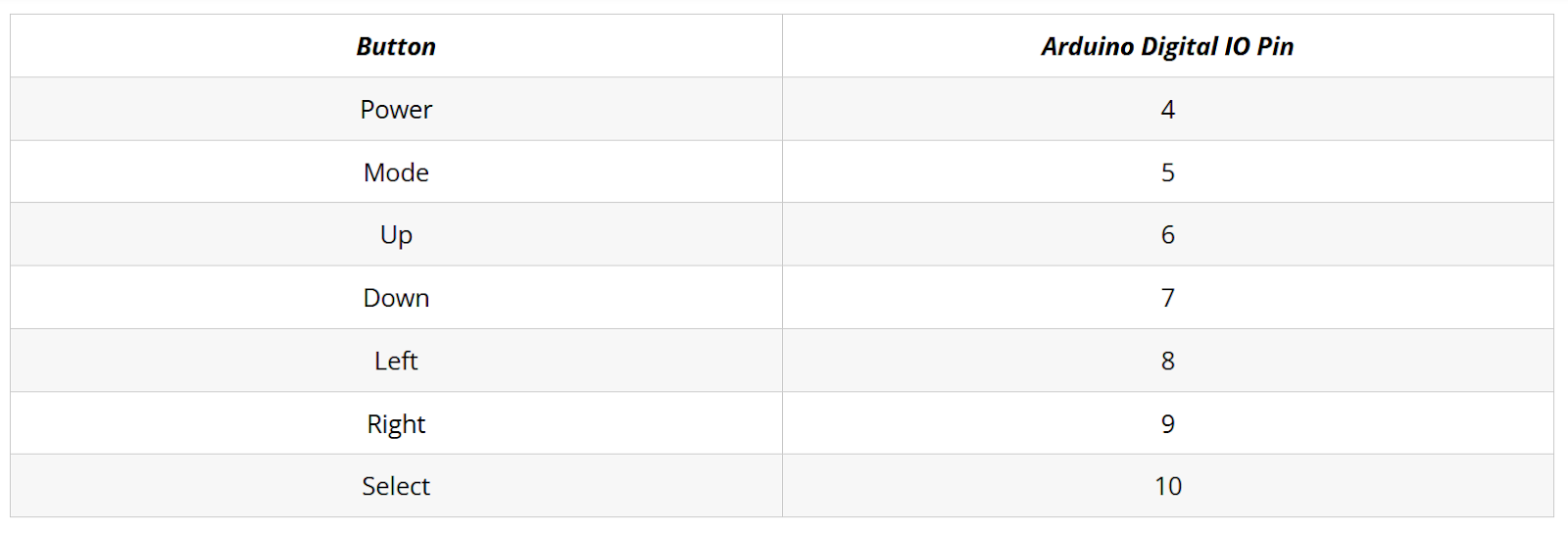
Table Showing Button Connections
Source: Self-designed.
Then, connect the Wakeup button to the Digital IO pin 2. Also, note that you’ll use the 10kΩ resistor to pull down the Digital IO pins. And you can pull up the other button pins internally.
Next, link the ends of your buttons (except the Wakeup button) to the GND, while the end of the Wakeup button goes to the VCC.
While at it, don’t forget to connect your CR2032 3V lithium batteries in series to power your circuit.
Arduino Code
Here’s the code you need for this project. Also, place the previous decoded values in the corresponding arrays for the TV and AC devices.
These arrays include: tv_onoff[], tv_voldown[], tv_prev[], tv_next[], tv_source[], ac_onoff[], ac_tempup[], ac_tempdown[], ac_fan[], ac_turbo[], and ac_swing[].
You can get the code for this project here.
Note: You only have to fill in the corresponding arrays for the device you want to control. Also, you’ll need the “LowPower” library to put the Arduino in sleep mode when it’s inactive.

DIY Remote Control Switch

Remote Control Switch
A remote control switch is another fun project you can try. It can turn ON/OFF your electronic devices. And you don’t need a microcontroller for this one. Here are the components you need:
- 1N34 diode (1)
- CD4017 IC (1)
- 80 cm Antenna (1)
- 1k resistor (2)
- LED (2)
- 100KR resistor (1)
- 6-turns Coil (1)
- 10k resistor (1)
- 1-35 pF variable capacitor (1)
- 120R resistor (1)
- 5 to 12v battery (1)
- 100Ω resistor (1)
- 5v relay (1)
- 390Ω resistor (1)
- 1N4007 diode (1)
- LM358 IC (2)
Circuit Schematic
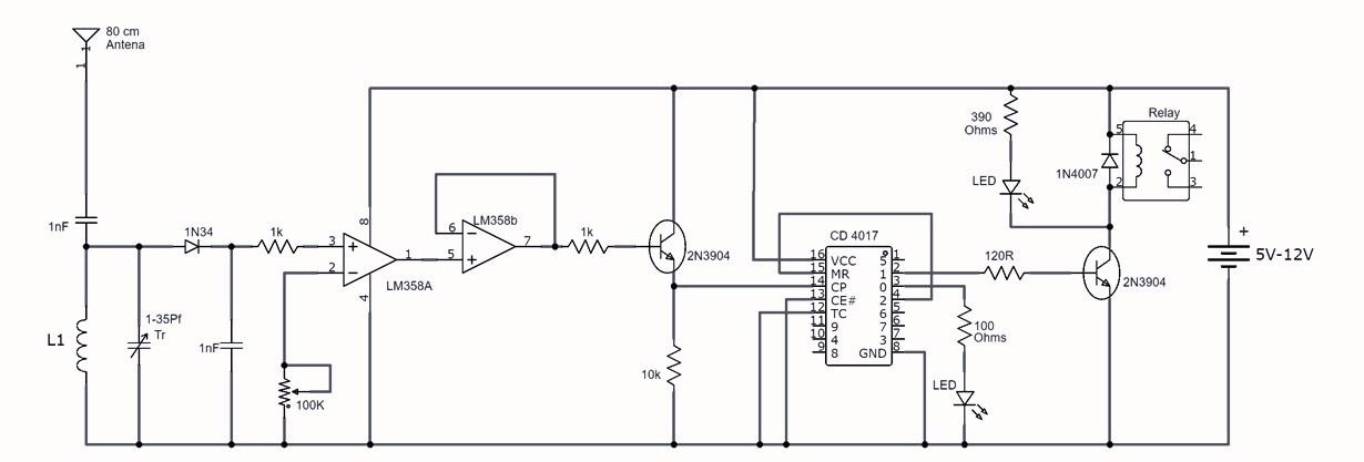
Remote Control Switch
Source: Drawn
How to Build
It’s easy to build this circuit. Follow the schematics above to know where and how to connect your components.
We recommend using a good-quality FM transmitter for the best performance. Also, you don’t need a microphone for your transmitter. The receiver circuit can detect RF signals over a solid range.
DIY Remote Control Car
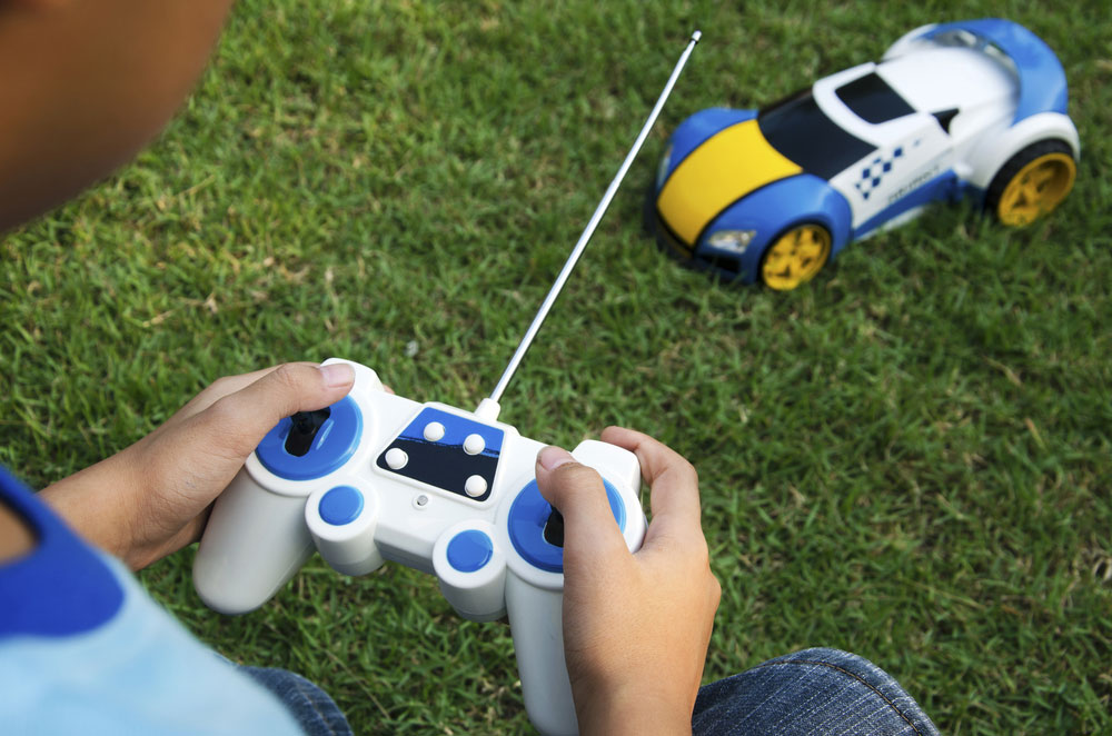
Remote Car Toy
We can use a couple of ICs and a motor to build a remote control car. But first, you’ll need to make a transmitter and receiver circuit. Here’s how:
Building a Transmitter
You need the following for a transmitter circuit:
- DPDT switches (2)
- 1M resistor
- RF transmitter module
- Power supply circuit
- HT12E encoder
Circuit Diagram
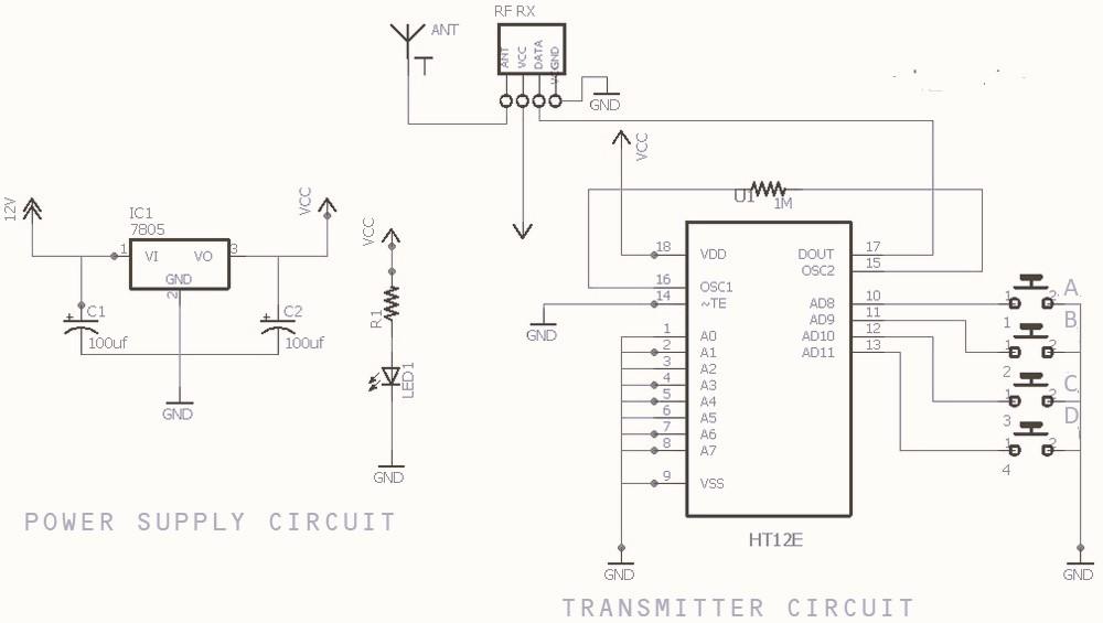
Transmitter Circuit
Source: Drawn
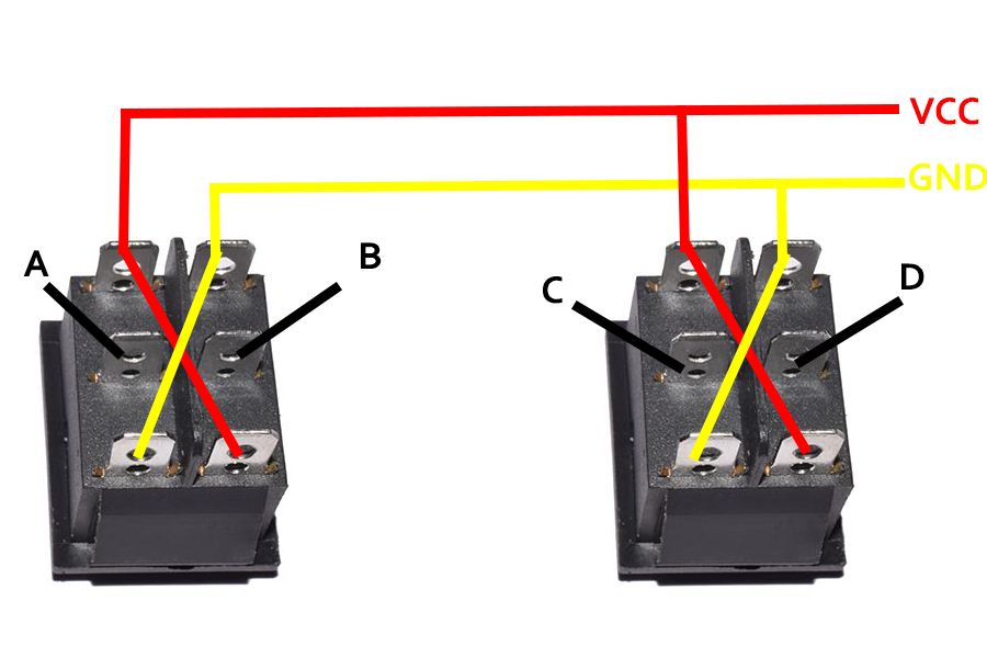
DPDT Switch Connection
Source: Self-designed
Note: look closely at the A, B, C, and D marking on the transmitter circuit and the DPDT switches. And ensure you connect the transmitter circuits, A, B, C, and D, to the ones marked on the DPDT switches. Also, you can power the transmitter circuit with a 9v battery.
Building a Reciever
Here’s what you need to construct a receiver circuit:
- HT12D decoder
- RF receiver module
- L293D motor driver
- Power supply circuit
Circuit Diagram
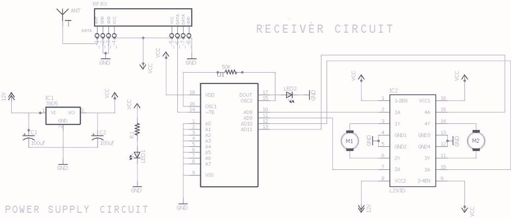
Receiver Circuit
Source: Drawn
How to Build
Follow the schematic above to wire the receiver circuit. We have two LEDs on this circuit: one of them lights up when you activate the power supply, and the other LED lights up when you supply power to the transmitter. And you can power the receiver circuit with a 12v supply.
Building the Remote Control Car Circuit
First, choose a suitable rotor. So, if it’s a small car, use a 6V Bo motor. If it’s big, then a 12v DC motor will suffice.
Also, you’ll need a suitable RPM for the ease of controlling your car. Here, we used a 12V motor with 300RPM.
Make your Connections
Here’s what you need for your connections:
- L293D IC
- Motor
- Chassis
- Breadboard
- Receiver Circuit
- HT12E and HT12D encoder and decoder
- LEDs (4)
- Push buttons (4)
1. First, place your IC on your breadboard. Then, connect the 5v(VCC) and GND. Also, attach the 12V to pin 8.
2. Second, link your motor’s enable pin to the VCC (5V) and supply power.
3. Use a multimeter to check the motor’s output pins. If you don’t get any readings, consider replacing your motor.
4. Next, connect HT12E’s (encoder) pin 7 to HT12D’s (decoder) pin 14.
5. Attach your push buttons to pins 10, 11, 12, and 13 of the HT12E. And link your LEDs to the same pins on the HT12D.
6. The LEDs should glow when you push the buttons. If it remains dark, debug or replace your RF module.
7. Lastly, assemble your circuits, motors, and wheels on your chassis. Then, test your RC car.
Rounding Up
Remote Control
With the right materials and guidance, DIY remote control projects can be fun to build. We covered a few projects in this article, like building a universal remote, remote control switch, car, and using your phone as a remote.
These are just some of what you can do with remote control. Feel free to reach us if you have any questions.


