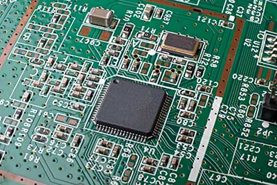
Are you designing a PCB and don’t know what substrate to use? Undeniably, substrates form an essential part of PCB manufacturing. And the first step to creating a high-quality PCB is choosing a suitable substrate. In truth, the FR-4 is a more common substrate for PCB manufacturing and is affordable. However, we’ll introduce you to another substrate type: IMS pcb.
In this article, you’ll learn everything about an IMS PCB and how it compares to the more common FR-4 PCB.
Are you ready? Let’s begin!
Contents
What is an IMS PCB?
The term IMS stands for insulated metal substrate. IMS PCBs have metallic support plates separated by a dielectric layer. Also, the circuit’s copper conductors are what generate this dielectric layer.
Interestingly, the dielectric layer’s purpose is to transfer heat to the metal substrate. In other words, the metal substrate is like a heat sink that absorbs excess heat from the circuit. Also, the metal substrate provides a sturdy structure for the PCB.
Additionally, dielectric layers have unique heat dissipation features. So, they can endure stress from high voltages. As a result, you can find IMS PCBs in circuits with severe heat generation.
The Advantages of IMS PCBs
FR4 PCBs put up a tough competition for IMS PCBs. However, this section will show you how well the IMS stands up to its competition. Here are the advantages of using IMS PCBs.
Structural Support
Thick metal substrates are sturdy and offer better structural support for circuits. Also, they serve as the main structure for different applications.
Electromagnetic Shield
Metal substrates also provide electromagnetic shields. Hence, you can use IMS as your circuit’s active ground plane. Undoubtedly, this active ground plane reduces the copper traces needed for your circuit, thereby reducing manufacturing costs.
Increased Thermal Conductivity
Metals are good heat conductors, so it makes sense that the IMS would have high thermal conductivity. And IMS PCBs have thermal conductivity capabilities up to 12 W/(m. K) and a maximum of 3.2mm metal thickness.
But that’s not all. Designers and manufacturers can leverage this increased thermal conductivity and include several heat-dissipating components in IMS PCBs. As a result, you’ll get better compactness overall.
Fire Immunity
Regular fires and heat from circuits can’t destroy metal. After all, IMS PCBs use metal substrates. Hence, they have more fire immunity than standard PCBs.
Hence, IMS PCBs are better options for high-power circuits or applications, especially when the circuit is in a high-temperature environment.
SMD (Surface-mount Device) Compatible
IMS PCBs are compatible with surface-mount devices. Why? Because IMS PCBs have high thermal conductivity. So, they can absorb any heat SMD components generate and dissipate it to avoid damage.

IMS vs. FR4
IMS and FR4 are excellent substrates with great benefits. But, you must understand the differences between these substrates to know which one fits your application.
Here are the differences between IMS and FR4.
Components
FR4 PCBs allow mounting of through-hole components. However, these PCBs must be single-layer PCBs. Contrary, single-layer IMS PCBs don’t allow through-hole components.
Thermal Conductivity
IMS PCBs offer increased thermal conductivity and can handle more heat-intensive applications. While the FR4 PCB also provides thermal conductivity, it can’t compare to IMS PCBs.
Solder Masks Colors
You’ll find that IMS PCBs feature white solder masks only. Contrarily, FR4 PCBs have three solder mask colors, including amber, green, and black.
Manufacturing Process
The manufacturing process for IMS PCBs is pretty complex and requires specific tools. For instance, manufacturers need diamond-coated saw blades to cut the metal substrate material.
However, FR4 PCBs have less complex manufacturing processes, and you can use standard machining tools.
Amount of Layers
You can add multiple copper layers to FR4 PCBs. In contrast, most IMS PCBs have single layers.
In truth, you won’t see a lot of multiple-layered IMS PCBs because of their complex manufacturing process.
Thickness Limit
Since there’s no limit to the number of layers you can add to an FR4 PCB, there’s also no limit to how thick they can get.
IMS PCBs, on the other hand, can’t be too thick. Otherwise, the PCB will lose most of its benefits if the thickness exceeds the limit.
Applications of IMS Boards
You can use IMS boards for various applications. Some of these applications include:
Power Electronics
Power electronic circuits have switching device capabilities. However, this feature generates a lot of heat, which can cause severe damage to the circuit if uncontrolled.
IMS boards have high heat dissipation capabilities, making them the go-to for power electronic circuits. Also, you won’t need to install heat sinks on every component, allowing you to create more compact designs.
LED Technology
IMS boards are perfect matches for LED technology. Although LED circuits are power-efficient and compact, they can generate high heat.
Thus, creating these circuits with an IMS board is the best option. After all, an IMS board absorbs and dissipates heat efficiently.
Solid State Relays
Another application that makes excellent use of the IMS board’s thermal conductivity is the Solid State Relay (SSR). SSRs are modernized versions of mechanical relays and often feature optocoupler driver circuits and power switching devices.
Also, SSRs have compact designs, which help to reduce the amount of heat generated. However, IMS PCBs still work in this application because they absorb heat and dissipate it into the small casing.
Automotive Industry
Advanced vehicles feature multiple control unit circuits. And these circuits are either near or in the engine of such cars. So, these circuits naturally work under high temperatures.
For this reason, IMS PCBs are excellent options. In short, these boards provide the necessary mechanical properties and thermal conductivity for these applications.
Different Types of IMS Boards
We have different types of IMS boards according to three categories: the type of metal substrates, PCB layer, and component mounting position.
Type of Metal Substrates
We have three types of IMS boards according to the metal substrate.
Copper Metal Substrate PCB
Copper substrate PCBs are pretty rare and expensive. They work for applications that require excellent electrical and thermal conductivity. While copper offers the best substrate material, it’s not immune to corrosion.
Aluminum Metal Substrate PCB
Aluminum substrate materials are more common and affordable. However, they only offer standard electrical properties and thermal conductivity.
Stainless Steel Metal Substrate PCB
Stainless steel substrate materials are cheaper than copper and aluminum substrates. Undoubtedly, these substrate materials can’t dish out excellent thermal and electrical performance. But they offer excellent mechanical strength.
PCB Layer and Component Mounting Position
We have four types of IMS PCBs according to the component mounting position and PCB layer.
Dual Component Mounting Side IMS PCBs
IMS PCBs with this design feature two solder mask layers. Interestingly, these solder mask layers can host different components.
Also, the design features the metal substrate in the middle and Vias–for transferring current and heat. Additionally, there’s resin material surrounding the vias and providing insulation.
IMS PCBs with this design can dish out increased mechanical performance and decent heat sink capabilities. However, such designs can only create complex circuits.
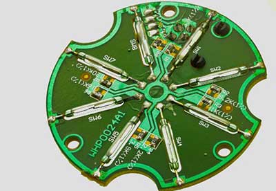
Single-Sided Metal Core IMS PCBs
IMS PCBs with this design feature only one solder mask layer. Also, it features one copper layer and a metal substrate at the bottom.
These designs work great for simple circuits like LEDs or SSRs. Also, the metal substrate at the bottom work as a heatsink.
Multilayer Dual Component-Mounting Side IMS PCBs
The multilayer IMS PCB layout is pretty complex. So, there are two dual solder masks for mounting components and several copper layers on both sides of the middle metal substrate.
You can use such IMS PCBs for complex circuits like SBCs (Single Board Computers). And the metal substrate is the heat sink that offers thermal conductivity.
Two Layers with Single Component Mounting Side IMS PCBs
This design has two copper layers with an FR4 layer in between. These designs allow you to integrate more complex circuits and reduce thermal conductivity.
Although the reduction in thermal conductivity is not so great, the design utilizes heat transferring vias as compensation. These vias can touch the bottom of SMD components and transfer heat to the substrate at the bottom.
IMS PCB Manufacturer
WellPCB
WellPCB is an advanced PCB manufacturer that offers a wide range of material options for PCB manufacturing, including Metal-based PCB.
The WellPCB also ensures high-quality control with an assembly process review. So, rest assured that you’ll get the highest quality products and services at the best prices.
Rounding Up
IMS PCBs offer various benefits that make them great for different applications. In addition, they have excellent heat resistance and can dissipate heat efficiently. Even the lowest metal substrate material has better thermal conductivity than most substrate materials.
IMS PCBs also offer mechanical performance and sturdy structures for your circuits. Plus, you can use a wide range of surface-mounted devices with an IMS PCB.
Feel free to contact us if you need an IMS PCB!