
Contents
Working Principle Of The Metal Detector Circuit
Metal detector circuits use an oscillator that produces alternating currents. An eddy current passes through the metal when active. Hence, the current produced passes through a coil. Doing this creates an alternating magnetic field.
The magnetic field attracts the metal closets to the coil. As a result, the metal changes the magnetic field linked to the metal. Consequently, the coil on the circuit detects a change in the magnetic field.
Advantages
- Metal detector circuits are simple and easy to use.
- Proximity sensors can function as microcontrollers.
Disadvantages
- Metal detectors have a short range of detection.
- Selective discrimination of non-metallic objects.
How To Build A Metal Detector
Jagadish Chandra Metal Detector Patent
Let us focus on building a simple circuit.
A Deep Dive Into The Components
TDA0161 Proximity Detector IC
The TDA0161 Proximity Detector IC detects metallic objects. It does this by detecting changes in Eddy’s current frequencies without delay.
With the help of a tuned circuit, the TDA0161 acts as an oscillator. All the changes in the supply current determine the output signal. When the current detects a high signal, then metal is present. But, if there is no presence of metal, the signal is low.
Generally, the TDA061 is a dual in-line package that has eight pins.
Receive Coil

Metal Detector Receive Coil
The receive coil comprises a 30 AWG enameled copper wire. Alternatively, you can swap it for any conductive material wound into a coil.
Once you wind up the received coil, you must double-check and confirm you have a 5.8 cm diameter. The total number of turns used to make this coil ranges from 140 to 150.
The Circuit
TDA0161 Metal Detector Circuit Diagram
The circuit that we will use for this example is an LC circuit. It has the inductor and the capacitor connected in parallel. The circuit resonates when there is a similar frequency material near it. Both the capacitors and indicators charge alternatively.
When the capacitor completely charges, the charge flows to the inductor. The inductor starts charging when the capacitor has no charge in other cases. For this, the capacitor draws charge from the inductor.
As a result, the inductor’s charge reduces. It leads to the capacitor charging process to fill the inductor following suit. In conclusion, the induction coils are magnetic field storage devices. On the other hand, capacitors are electric field storage devices.
Detailed Explanation Of The Circuit And Results
You connected all your components and laid them out, so it is now time to start. Let us dive deep into the experiment.
- The LC circuit, including the L1 and C1, gets any resonating frequency to a metal close. As a result, the metal and magnet attraction will create an electric field. The result will lead to the induction of current in the coil. Lastly, it will change the signal flow through the receive coil.
- The variable resistor will change the proximity sensor value to equal the LC circuit. During the experiment, check the value scored when the receive coil is not close to any metal. Once the receive coil detects metal, the phase feedback signals will change.
- The proximity detector will detect the signal change and react. The output signals from the proximity sensor will be 1mA when there is no metal detection. If there is any metal detection, the result will be 10mA.
- Once the output is high, the R3 resistor will show a positive voltage to the Q1 transistor. As a result, Q1 will turn on, leading to the LED glowing. Later, the buzzer will buzz or have an audio signal. The R2 resistor will eventually limit the current flow.
Metal Detector Using Arduino UNO
Arduino Uno
You can also build a simple yet effective metal detector using an Arduino. Your supplies will vary. You will also have to do some coding. If you choose to go this route, the common components will include:
- Trigger button
- A side button is used to set the frequency
- Switch
- 3 AA batteries – 4.5 Volts
- A motor
- Simple circular head
- LEDs
- A coil of wire
- Potentiometer
- Speaker
- Conductive object
Once you have your circuit connected, your schematics should look like this.
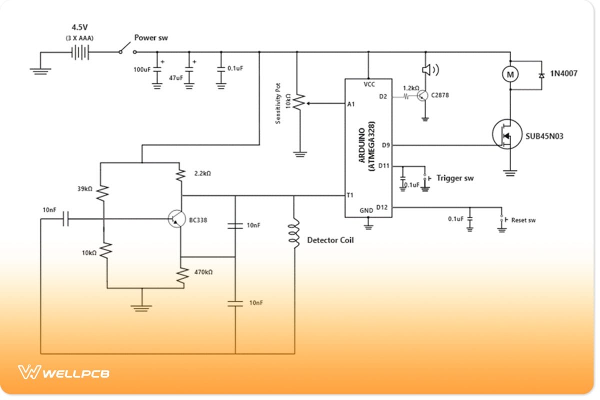
Arduino Metal Detector Schematic Diagram
The above setup uses an Arduino UNO to program a DIP ATMega328. For starters, remove the ATMega328 from the development board. You will add the ATMega328 and the other circuit parts to a preboard.
The battery pack powers the ATmega328. It also powers the oscillator and the motor with LEDs.
Now, it is time to write your code. To begin with, you need a proper understanding of simple programming principles. You will need setup functions, interrupt functions, and loop functions.
Your code should look like this:
Setup Function

Metal Detector Setup Function
Interrupt Function

Metal Detector Interrupt Function
Loop Function

Metal Detector Loop Function
Using this circuit, you can pick up conductive objects. These include small metal objects using the coil with the lowest sensitivity setting.
You can pick up steel rings, coins, and screws with the highest setting. If you want to extend the detector’s range, you need to increase the current flow through the inductor.
For the most part, a double power supply will suffice. Generally, you can increase the number of wire wraps used to make the coil.
There is a learning curve to this build. It is, nonetheless, more advanced. With this in mind, this circuit can do more than simple circuits. This circuit can build a wide range of detectors in the long run.
For example, a hand-held metal detector and even a portable art metal detector. If you choose to go big, you can build an industrial metal detector.
Applications

Using a metal detector for treasure hunting
- Metal identification like gold, iron, or silver.
- Scan for metal objects, unwanted objects, and inorganic materials.
- Mapping of geological structures.
Conclusion
The bounds by which you can experiment using metal detector circuits are limitless. You can try innovating or even inventing based on the knowledge you now have.
In conclusion, if this piece hinted at something that you found interesting, you are in the right place. When you are ready to explore the circuit world further, do not hesitate to reach out to us. We are open to meeting all your PCB needs to develop detectors.


