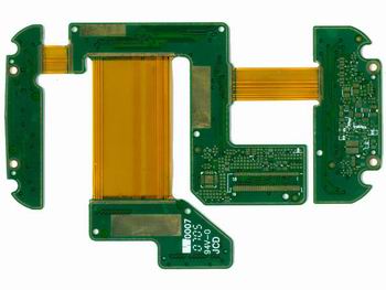
As the name implies, the Rigid-Flex PCB is the combination of rigid PCB and flex PCB. This combination makes it suitable to be used in various applications, including military, telecom, and aerospace. The Rigid-Flex PCBs have around two or more conducting layers. Between them is the flex or rigid insulation material.
Contents
- 1 1.Rigid-Flex PCBs—Advantages of Rigid Flex PCBs
- 2 2.Rigid-Flex PCBs—Application of Rigid Flex PCBs
- 3 3.Disadvantages of Rigid Flex PCBs
- 4 4.Rigid-Flex PCBs—Structure of Rigid Flex PCBs
- 5 5.Manufacturing Technology
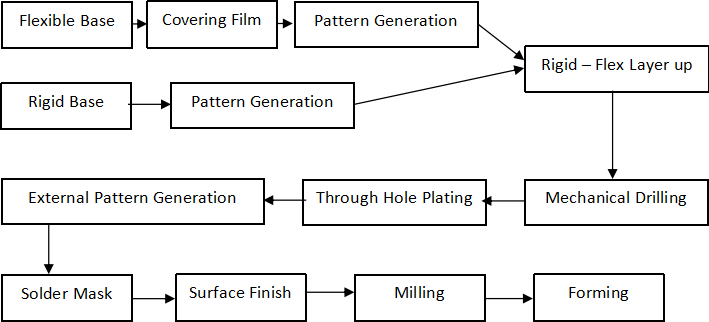
- 6 The step by step manufacturing process of Rigid-Flex PCB is given below
- 7 Embedded Flexible PCBs
1.Rigid-Flex PCBs—Advantages of Rigid Flex PCBs
They offer a very tight board size means more components in less space. Require less maintenance due to few interconnects. Can perform in a stringent environment.
Improved shock and vibration performance. Less weight and size. The problem of loose connections can be significantly overcome in flex and rigid circuit boards connected permanently. When rigid-flex PCBs. The thermal dissipation is also very efficient. The flexible part of the rigid-flex PCB can be bend at any angle without a break, and mechanical and electrical qualities are excellent.
They are excellent for 3D enclosure assembly, where PCB needs to be fitted anywhere on three axes. This high degree of flexibility makes them best for almost all advanced electronic devices/gadgets. The high dielectric strength enables it to operate in harsh environments, high-frequency signal transmitting, and impedance controlled systems.
2.Rigid-Flex PCBs—Application of Rigid Flex PCBs
Portable electronics, wearable electronics, Internet of Things and medical, etc.Hearing Aids, Night Visions, Portable CT scanner, Insulin Pumps, Battery Chargers.
3.Disadvantages of Rigid Flex PCBs
Complex manufacturing technology, long processing cycles, and manufacturing cost are high.

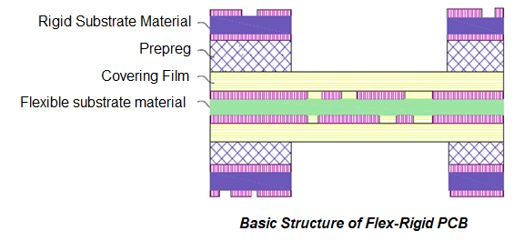
4.Rigid-Flex PCBs—Structure of Rigid Flex PCBs
The circuits belonging to the rigid part are interconnected with the flex part through plated vias. It contains one or more flex and inflexible PCBs, as shown in the diagram above.
5.Manufacturing Technology
The arrival of flex-rigid PCB has revolutionized electronic products in the sense of quality and reliability. Now with this technology, the product volume can be decreased enormously. This will help replace harness and connectors efficiently, which turns into a reliable end product.
According to the latest technology in Rigid-Flex circuits, the FR4 glass fiber epoxy resin is used as an external rigid board also solder mask is used to guard the pattern of the challenging course.
As for the flex circuit substrate, the PI (Polyimide) board with a double layer is covered with copper is used as a flexible circuit core. At the same time, the acrylic or polyimide film is applied to protect the pattern of the flex circuit.
The topmost materials for adhesive films contain polyester, epoxy, and acrylic. They have excellent heat resistance, excellent flexibility, and authoritarian chemical resilience. The low flow pre-preg is used for adhesion. However, the coefficient of thermal expansion is low for epoxy resin and is used to join the internal layer with the covering layer.
The comparison of 3 common Materials of the substrate of Rigid-Flex PCBs is shown below.
|
Feature |
Polyester |
Polyimide |
PTFE(Polytetrafluoroethylene) |
|
Limit Tension/N*mm2 |
172 |
172 |
20.7 |
|
Limit Elongation/% |
120 |
70 |
300 |
|
Flammability |
Flammable |
Self-Extinguishing |
Inflammable |
|
Dielectric Strength mV*m |
300 |
275 |
17 |
|
Moisture Absorption / % |
<0.8 |
2.7 |
0.01 |
|
Heat Resistance / oC |
150 |
400 |
260 |
The step by step manufacturing process of Rigid-Flex PCB is given below
Embedded Flexible PCBs
There is a new type of Rigid-Flex circuit introduce. This is the embedded flex circuit in which the flex circuit substrate is embedded inside the rigid internal board. The interconnections between wooden and flex boards are not available, but it is obtained using buried vias or blind vias.
In this type of circuit, the wastage of rigid PCB substrate is significantly reduced, and the usage of flex substrate is greatly increased. It contains the advantages of High-Density Interconnect (HDI) PCBs.