Contents
Smoke Detecting Circuit–Safety precautions
The smoke sensing circuit is susceptible to all kinds of smoke. Therefore you need to be very careful if you have the sensor circuit in your house or room and a regular smoker. This is because the sensor circuit will trigger the alarm or buzzer each time it senses the smoke of the cigarettes.
Notes
- The circuit is working at very low voltages.
- There is no need to have additional capacitors in the circuit.
- There is a need for a variable DC supply in the circuit.
Smoke Detecting Circuit–Components Required
The following are the basic components required to make the smoke-detecting circuit.
- Bread Board
- BC547
- 10k POT
- Smoke Sensor (MQ6)
- Resistors of 1K
- Variable Power Supply
- Connecting wire
- Buzzer
- LED
- Jumper wire

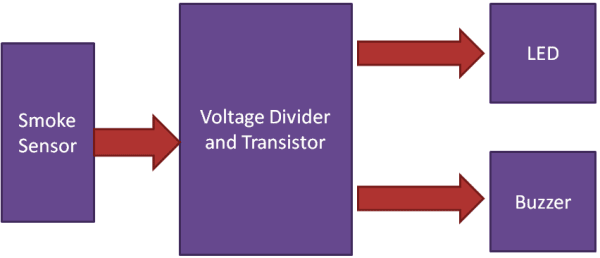
Smoke Detecting Circuit–Chart Flow Diagram
The following is the chart flow diagram.
Basic Circuit Diagram
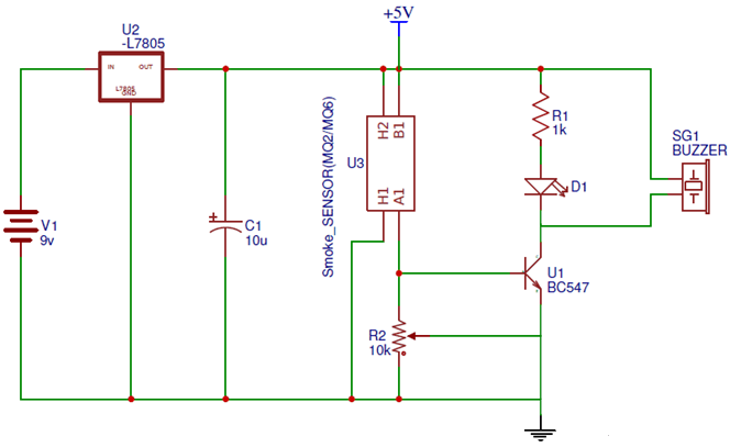
Working Principle
The circuit has the MQ6 smoke, also known as the Gas sensor gadget, used for smoke or fire detecting in the air. The transistor, i.e., BC547 NPN, is used for the buzzer or alarm trigger. The 10K potentiometer is used for the calibration of the circuit. In contrast, the circuit is designed to have a voltage divider circuit being used with the MQ6 smoke sensor and the potentiometer. The value of the MQ6 is changing whenever it senses smoke as it has a resistance.
The transistor operating properties are being used to work in the circuit of smoke detection. The NPN BC 547 transistor is being used, which is turned ON only at 0.7V at its base, and the topology being used in the circuit is voltage divider biased. The potentiometer is being used for calibration purposes. Whenever voltage is applied at the base terminal, which is less or greater than 0.7V, which would turn ON the transistor, the smoke sensor would sense the smoke and reduce the device’s resistance, i.e., the MQ6 smoke detector. Due to this decrease in the resistance, the voltage across the base of the BC547 is increased to 0.7V. This, in turn, makes the transistor ON and LED lights up, and the buzzer is triggered to start beeping. When the smoke has vanished, the detector is made OFF, and the voltage across the base of the transistor is reduced to a value below 0.7V.
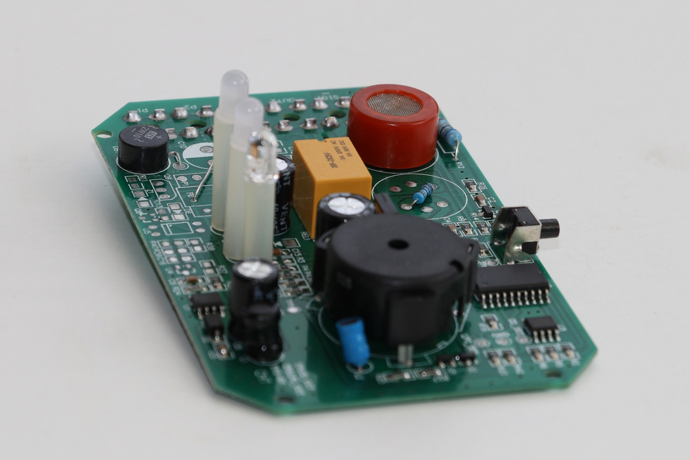
Photo of the Smoke Detecting Circuit