Contents
Basic Components of a Cell Phone
Here are some essential components of a cell phone that will help you understand how a phone works:
Keyboard and LCD Screen
The keyboard and LCD screen are vital pairs of channels that allow you to communicate with your phone.

Phone keyboard and LCD screen
So, all you need to do is issue data and commands to your phone by pressing the keyboard buttons.
The LCD screen will relay nonverbal data to you based on your keyboard input, like missed calls, text messages, dialed numbers, etc. Also, this pair can handle status reports, commands, etc.
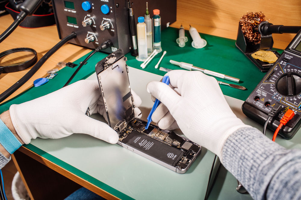
A technician removing LCD screens of phones
Microphone and Speaker
With these components, your device will communicate messages from other customers to you. When you speak into your microphone, it changes sound to electricity. Then, the electric signals digitalize and transmit out via the antenna.
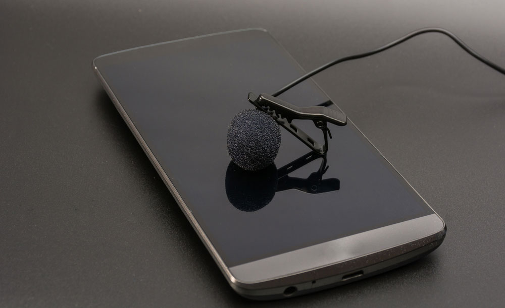
Phone Microphone and speaker
Also, when someone speaks to you, the signal will hit the antenna. Then, it becomes un-digitized and moves to your speaker to convert the electrical signals into sounds.
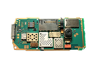
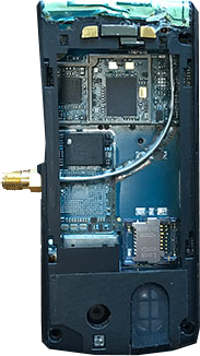
Circuit Board
Phone circuit board
This component is responsible for controlling how your phone works. It has a collection of features like a vibrator and buzzer that alerts you of a sim card, incoming phone calls, emergency calls, etc.
Battery and Antenna
The battery brings life to a cell phone. So, without it, nothing happens on your cell phone. And it’s one of the first things you’ll see when you open your phone.

Phone battery
On the other hand, the antenna is a portal where your phone links to other phones. Further, in most phones, the antenna has a coil of circuit wires that attach to a cover (removable)—that’s easy to break.
Phone antenna
Source: Wikiwand
How Do Cell Phone Circuit Boards Work?
The circuit board is the brain area of the phone. But it can run the entire system to ensure that the cell phone works appropriately by working with the following components:
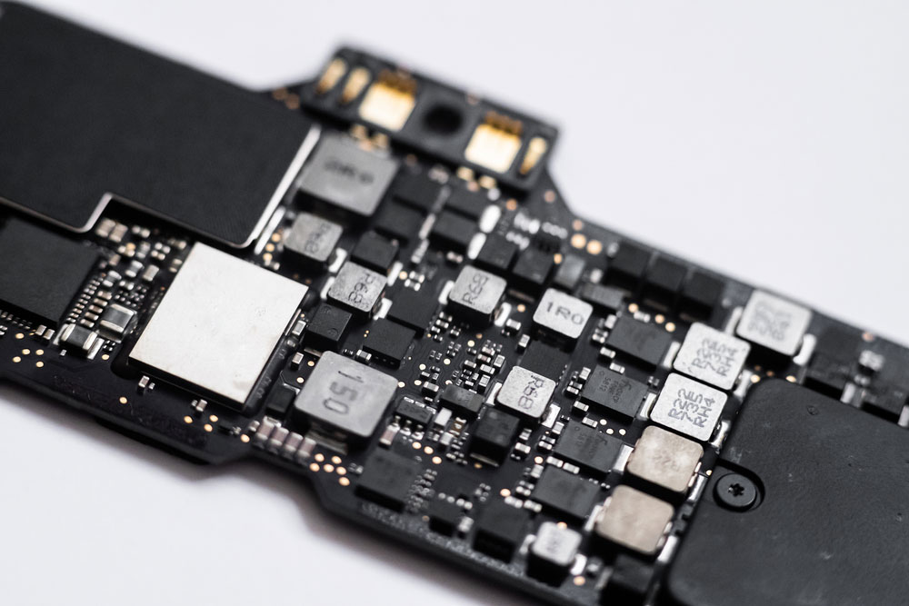
Computer Chips
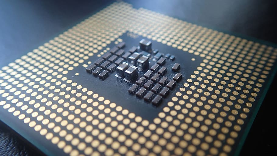
Computer chips
Source: Piqsels
Circuit boards have a few computer chips. These components are responsible for doing digital-to-analog and analog-to-digital conversion within the board.
In other words, the computer chips change outgoing audio signals from analog to digital. Then, it changes audio signals from digital to analog.
Further, the board’s signal processor has a rating of 40 million instructions per second (MIPS) functions. This helps to conduct signal manipulation calculations speedily. Plus, it handles both signal compression and decompression.
Flash Memory and ROM Chips
Phone Memory chip
These components serve as the phone’s storage location. And they help to store the cell phone’s entire operating system and customizable options. Also, the circuit board uses the power and radio frequency sections to manage power and phone recharging.
In addition, the flash memory and ROM chips control various FM channels.
Microprocessor
Phone Microprocessor
Source: Max Pixel
The microprocessor handles the cell phone’s keyboard and display area tasks. Also, it pays attention to the phone’s command options and control signals. Further, the microprocessor interconnects the main functions of the keyboard.

Simple Cell Phone Detector Circuit
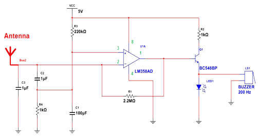
Cell Phone detector circuit
Source: Researchgate ℅ Hamzah M. Marhoon
This simple cell phone detector circuit uses some passive components and an Op-amp. Here are the parts you need for this project:
- Capacitors:
- 0.22µF ceramic (1)
- 100µF/25V electrolytic (1)
- 22pf ceramic (3)
- 0.1µF polyester/ceramic (1)
- BC548 (1)
- Resistors (all ¼ Watts):
- 1KΩ (1)
- 100KΩ (1)
- 2.2MΩ (1)
- 1.2MΩ (1)
Working Principle
It’s important to note that you can’t use an ordinary RF detector for tuning LC circuits. And that’s because they aren’t ideal for detecting signals in a mobile phone’s GHz frequency.
That said, the mobile phone has a wavelength that ranges from 3.3 to 10 cm and a transmission frequency of 0.9 to 3 GHz. Hence, it would help if you had a circuit to spot gigahertz signals needed for a mobile bug.
The process starts with the circuit’s C3 or 0.22µF disk capacitor getting the cell phone’s RF signals. Then, the capacitor’s lead length (18mm) with a spacing of about 8mm fetches the preferred frequency.
So, the disk capacitor behaves like a small GHz loop antenna. Plus, the trap cell phone’s RF signals.
Moreover, the op-amp connects with the C3, which combines its non-inverting and inverting inputs.
And they both form a current-to-voltage converter.
Also, this circuit is a CMOS version whose input uses gated-protected p-channel MOSFET transistors. Further, this helps to offer low input current, high-speed performance, and high input impedance.
So, the output CMOS transistor can move the output voltage to about 10mV of each supply voltage terminal. That said, the C3 combines with the lead inductance and behaves like a transmission line that interrupts cell phone signals.
Hence, the capacitor generates a field. The field stores and transfers energy, like the minute current, to the IC1’s input. Consequently, this will distort the IC1’s balanced information and change the wind into the matching output voltage.
Second Stage
The R1 (high-value resistor) and capacitor C4 ensure that the inverting input remains stable. Hence, the output will have an easy swing to a high state. R2, on the other hand, offers C4’s discharge path. And when the work is high, the R3 (feedback resistor) will make the inverting input high.
Then, connect your C5 across the IC1’s pin eight and 1. Consequently, you’ll have to gain control and phase compensation to enhance the frequency response.
So, when C3 gets the cell phone detector signal, the LED will indicate a high and low output. As a result, the monostable timer will trigger via the C7. And the C6 will retain the transistor’s base bias for fast switching action.
Also, the capacitors and resistors (the low-value timing parts) will generate a short time delay. You can compactly assemble this circuit on a standard PCB and place it in a small box or junk mobile case with this setup.
Applications
- Detecting mobile phones in an environment
- Discovering stolen mobile phones
- For finding spy cell phones that have unauthorized transmission of video and audio
Limitations
The circuit is a low-range detector.
Final Thoughts
Phone circuits play a significant role as the brain of cell phones. But this circuit can only function by initiating other circuit board components like the battery, LCD screen, keypad, speaker, etc.
Also, you can set up a simple mobile detector circuit that will help discover stolen mobile phones, desk phones, or spy cell phones in a specific range of diameter.
But this project comes with a snag: a low-range detector. That is, the setup may be unable to detect a phone that may be far from the circuit’s range.
Do you need help with building a simple mobile detect circuit? Or do you want to get the best phone circuit for your projects? Feel free to contact us.


