
The principle of transformer is one of the most important electrical components in an AC power system. Today, many circuits use transformers which are essential and make up the backbone of how we power everything.
This article will teach you about its working principle, basic structure, and applications so that you can find the right transformer for your needs!
This article will teach you about its working principle, basic structure, and applications so that you can find the right transformer for your needs!
Contents
1. What is a transformer?
A transformer is an electrical device used to transmit electrical energy from one electrical circuit to another. Moreover, it maintains the power factor at unity and ensures voltage levels remain unchanged in both circuits.
2. Types of Transformers:
The types of transformers classifications are as follows:
(Transformer diagrams)
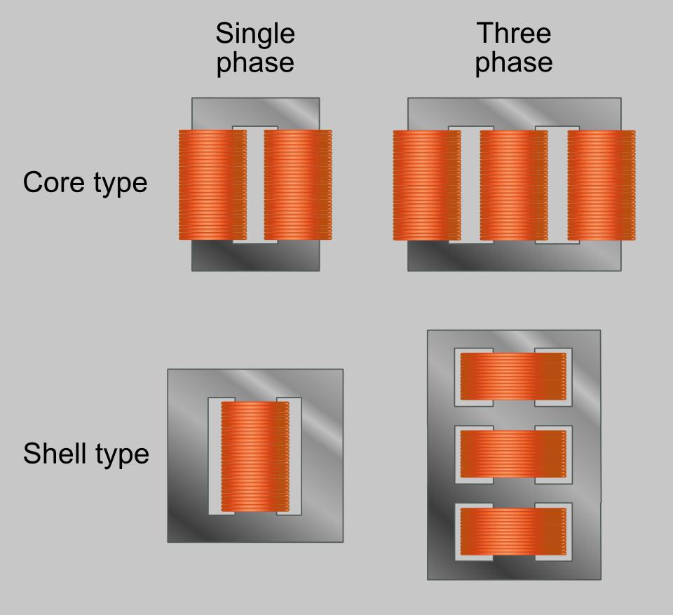
Based on construction
- Core type transformer- The core components may consist of laminated sheets of steel, silicon steel sheets, or iron alloy like -silicon steel. Also has cylindrical coils of wire as its windings with low voltage windings placed closer to the core.
- Shell type transformer- is one in which houses all the core, coil, and insulation inside an aluminum or steel shell. Mostly takes the rectangular form.
Based on the type of supply
- Single-phase transformer – This type is a single winding device with one coil connected to the primary side and another to the secondary side of a transformer.
- Three-phase transformer – Consists of three coils attached to each core side. Moreover, each coil connection is in such a way that they produce mutually perpendicular magnetic fields.
- Auto-transformer – This type uses two windings on either side for both step-up and step-down voltage transformation.
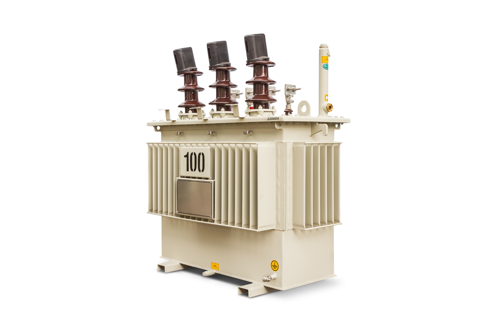
(Oil-filled transformer)
Based on cooling type
- Oil-filled transformers- It dissipates heat generated by the electric current through the medium of oil.
- Air core transformer- one in which it dissipates the heat generated by the electric current through the air.
Based on their use
- Current transformer- Used to measure very high currents in electric power transmission.
- Potential transformer- Measures very high AC voltages.
Based on the purpose
- Step-up transformer- provides the function of changing the voltage level from low to high
- Step down transformer- provides the function of changing the voltage level from high to low
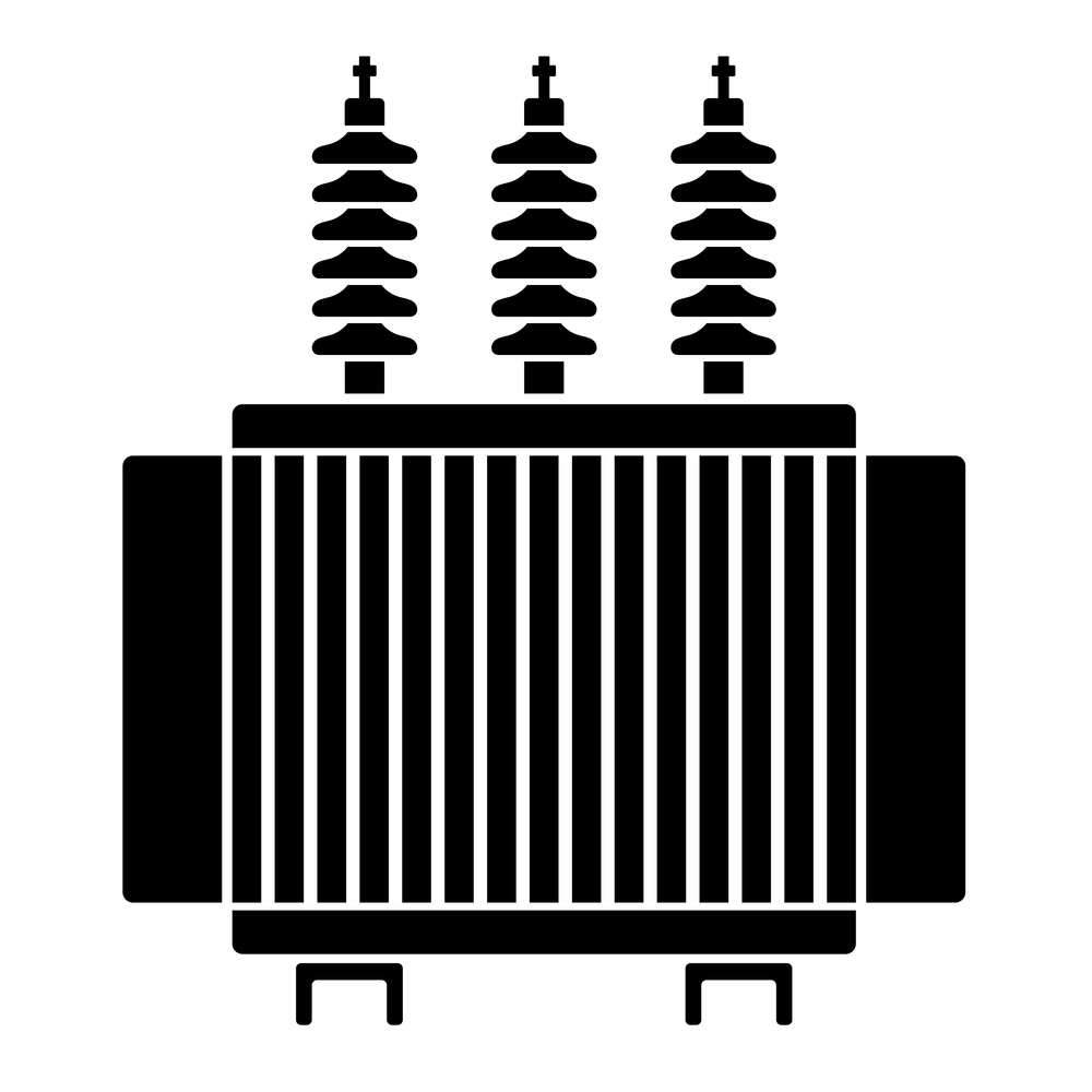
(High voltage transformer)
3. Applications of transformers
Transformers applications are in:
- Firstly, industrial and laboratory use and voltage regulation in power systems to increase or decrease supply voltage.
- Secondly, electric power generation and distribution, and mining, oil & gas industries.
- Thirdly, step up or step down AC voltages of electric power supply lines.
- Radio technology usage to step up or step down high-frequency signals for transmission over longer distances without any loss of signal strength. Common in audio transformers and commercial transformers.
- Lastly, Power electronics circuits where they can work as automatic voltage regulators.

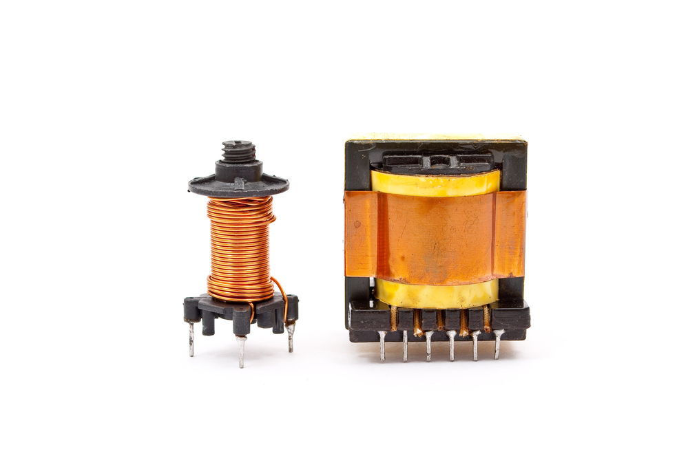
4. Basic Structures of a Transformer
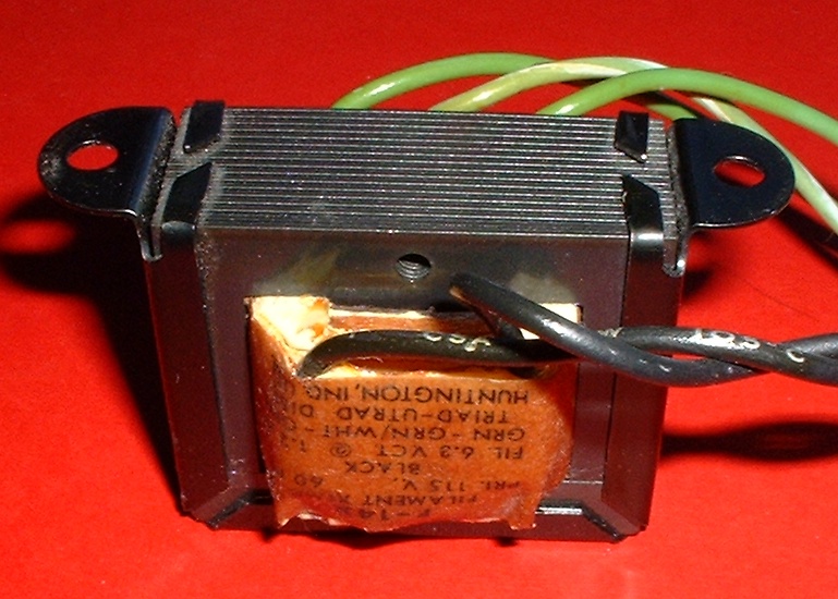
(Transformer structures)
The structures of a basic transformer include:
- Laminated core; made up of laminated iron pieces arranged in such a way as to provide a minimum path for magnetic flux. Also, the core acts as a closed magnetic circuit.
- Primary winding; placed around the core in either direction and insulated from the core. The coils are copper wires.
- Secondary winding; placed around the primary and insulated from it, both in the same direction or with reverse polarity to that of primary.
Basic Transformer Construction:
A transformer consists of two or more coils (windings) wrapped around a laminated steel core. The input windings (primary winding) connect to one terminal of the power source. And output windings (secondary winding) connect across the load circuit.

(Hand working on components)
The following are the basic steps in the construction of a transformer:
- First, making of primary and secondary coils – Use insulation tape or enamel coating to separate windings of these coils from each other.
- Next, mounting these coils on a common soft iron core consists of highly laminated silicon steel sheets wrapped with insulation tape to reduce eddy current losses. The joining of these transformer core laminations is in the form of strips. Importantly, the sheets should have high silicon content to lower hysteresis loss. Further, the primary coil connects to one end of the core while the other attaches to the secondary coil. Also, you need suitable bushings when insulating and bringing out terminals from the transformer tank.
- Shielding coils – Used to protect primary winding from electromagnetic effects caused by induced voltages in transformers that may cause catastrophic transformer failure. Similarly, this is done by wrapping additional insulation tapes on both sides of these coils.
5. Working principle of a transformer
The basic principle involved in transformers’ working is Faraday’s law of electromagnetic induction: N*dΦ/dt (Faraday’s Law), where N is the number of coil turns.
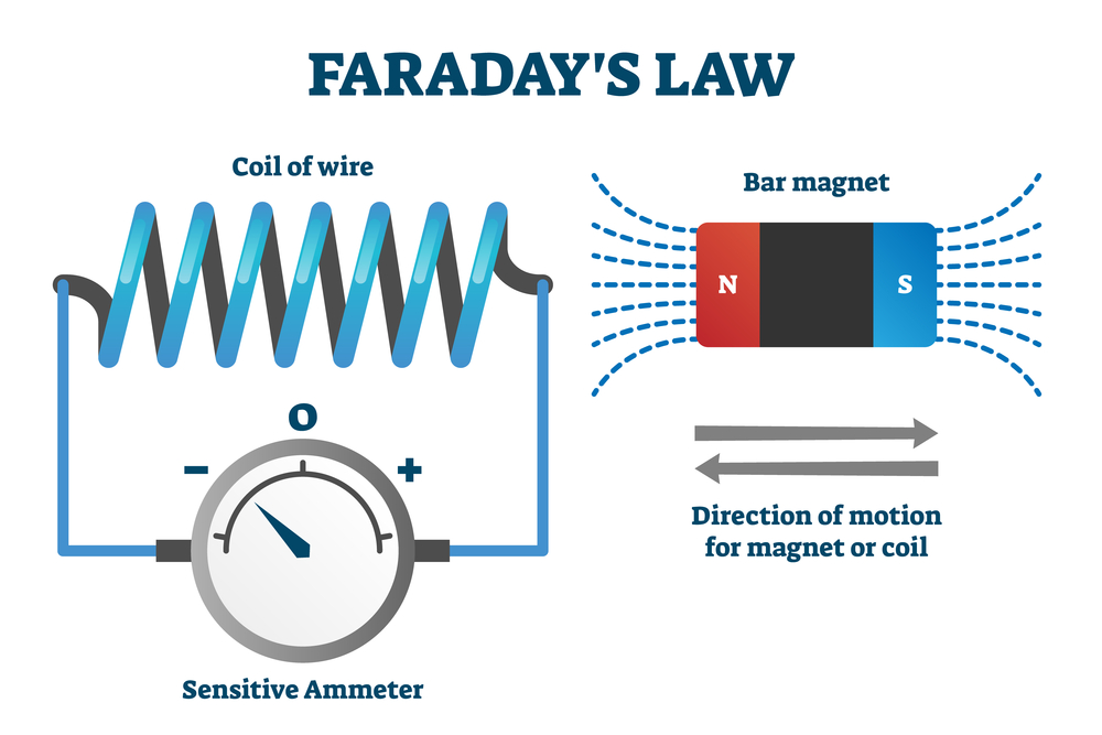
(Faraday Law)
The law states that an electric flux gets induced in a closed circuit when the magnetic flux linked with it changes. This phenomenon results due to the mutual inductance of currents present through these two circuits. Here’s the explanation:
When an electric current flows through the primary winding, it creates a magnetic field around this winding. Hence, produces a magnetic flux around the primary coil as well. Then, the transformer core provides a path for this flux to connect the windings. However, not all the flux links with the secondary winding and thus named leakage flux. Afterward, an induction of voltage on the secondary coil occurs. This is because of mutual induction between coils wound on a common iron core through coupling in the magnetic core.
This process creates induced emf as it tries to oppose the current flow through it and vice versa. The induced voltage in the secondary coil acts as a load for the primary winding.
NB; A transformer is a static device; thus the changing voltage levels occur due to magnetic induction, not by the movement of its solid materials.
Now, let us see important terms when dealing with transformers.

(Copper windings)
Turn ratio in transformers
The ratio of the number of turns in the primary winding to that in the secondary coil. This number denotes how many times the voltage level reduces in the primary circuit after getting stepped down through the transformer.
Its representation is X/Y. ‘X’ denotes the number of turns in the primary coil(Np) and ‘Y’ denotes the number of turns in the secondary coil(Ns). Assuming that it is an ideal transformer.
Formula; Np/Ns=n=Turn Ratio
For example, if there are 100 turns in the primary coil and 50 turns in secondary, this ratio gets expressed as 100/50.
This means a transformer with a step-up ratio will have fewer turns on its secondary side than its primary. However, the opposite is true for a transformer with a step-down ratio.
(Transformer windings)
Transformer ratio
The ratio of secondary voltage to primary voltage is the transformer ratio. The expression of voltage transformation ratio is in volts/volts or amps/amps, and this depends on the type of load resistor connected with the secondary coil.
The calculation formula;
Transformer ratio = (V/V or V/A secondary load resistor)/(V primary or A primary)
For example; The voltage across a secondary winding is 100 volts, and the current flowing through it is 20 amps. Then, the transformer ratio of that particular circuit will be 100/20.
NB; The maximum current level or voltage across a secondary winding in a transformer refers to the rated current or voltage. This rating of the secondary circuit decides its maximum working capacity. And determines whether it’s suitable for high voltage or low current applications.
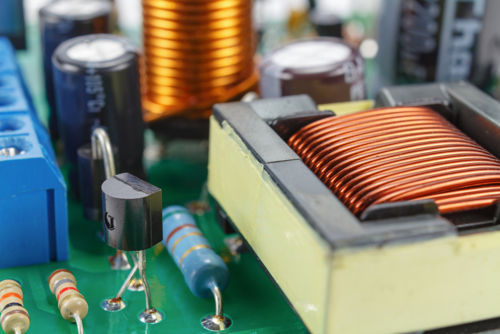
( The Transformer and electrical components)
Transformer efficiency
This is the ratio of work done by a transformer on input power to that generated in the secondary winding.
Its expression is in percentage terms.
The formula is:
Efficiency = (Output power/Input power) x 100
For example, consider a transformer’s input power 100 watts and secondary winding generates 80 watts. Then, the transformer efficiency of that particular circuit will be 80%.
This means there is a 20% loss in energy when power flows from the primary-secondary side of the transformer.
Note, both transformer’s input and output power levels must be the same for this ratio to remain valid. That is to say, and both primary and secondary currents must have the same value.
If the input current is greater than output, then the transformer efficiency will be less than 100% and vice versa.

(emf)
Electromotive force equation of a transformer
Electromotive force(emf) is simply the ratio of input voltage to output voltage in a transformer.
Its expression is in terms of volts/volt or amps/amp.
For example, consider the transformer’s input voltage like 100 volts and the output voltage is 95 volts. Then, the back emf of that particular circuit will be 95/100 or 0.95 times the input voltage.
This means there is a loss of 0.05 volt in energy when power flows from the transformer’s primary to the secondary side.
The formula for finding emf across a secondary coil of a transformer is:
E=N*delta/Turns^n
Where,
E: electromotive force in volts.
N: number of turns in the primary winding.
Delta/Turns^n: turns ratio of primary and secondary coils.
You can write the above equation as E=N*Turns^(n-x)
Where ‘n’ denotes the number of turns in the secondary coil, and ‘x’ is equal to (N-n).
This equation shows that emf across a secondary winding is directly proportional to primary turns and inversely proportional to (N-n).
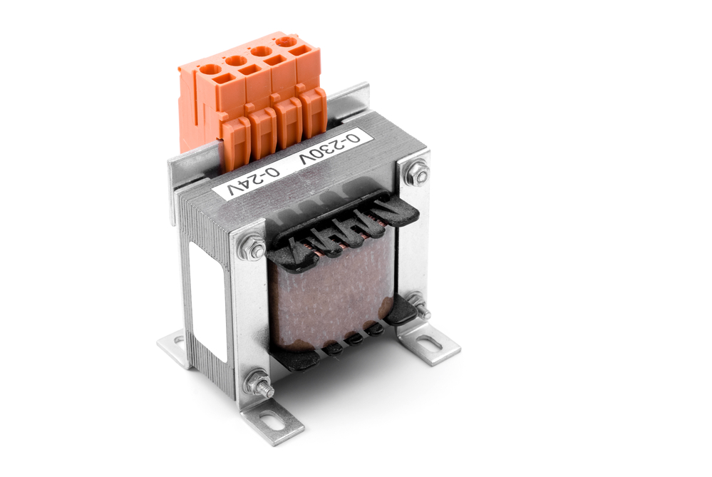
(Voltage transformer)
Electrical power in a transformer
Calculating the electrical power in a transformer is easy, using the Formula: Power = Voltage x Current.
Where ‘Power’ denotes the input power and ‘Voltage’ and ‘Current’ denote input voltage and current.
For example: Consider the transformer’s power rating as 100 watts and the voltage across its primary winding is 400 volts. Then, the current flowing through it will be 0.25 amps as power=voltage x current.
As you can see here, the current drawn by a transformer is very small compared to its power rating.
6. Summary
We’ve given information on what transformers do and how they work in this blog post. If you’re interested in learning more about your transformer-related project, contact us! Our team is always happy to answer any questions from you.


