Contents
- 1 What Is a TQFP?
- 2 What is an LQFP?
- 3 TQFP vs. LQFP: Key Differences
- 4 QFN vs. QFP
- 5 How Does a Thin Quad Flat Package (TQFP) Work?
- 6 What Industry Problems Does the TQFP Address?
- 7 What Are the Benefits of a TQFP?
- 8 Benefits of TQFP’s Surface Mount Technology (SMT)
- 9 How Gate Arrays Address TQFP Spacing Limitations
- 10 What Is the Difference Between a TQFP and a Small Outline Integrated Circuit (SOIC)?
- 11 What Are the Different Types of QFPs?
- 12 Costs Associated with TQFPs
- 13 TQFP vs. LQFP: Conclusion
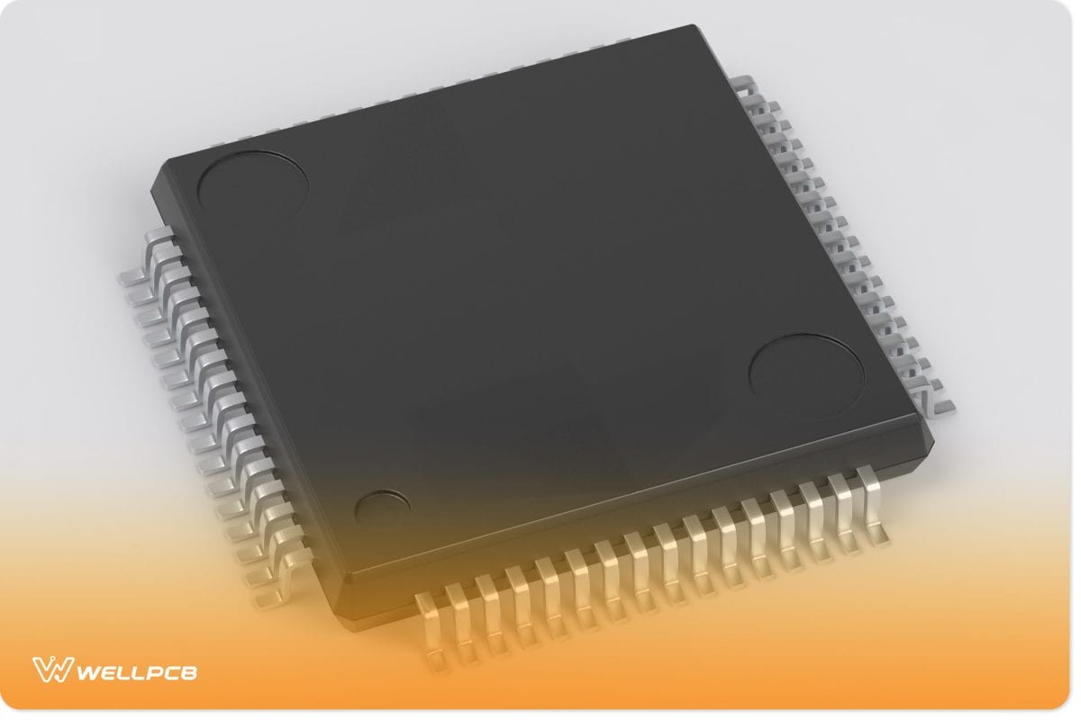
What Is a TQFP?

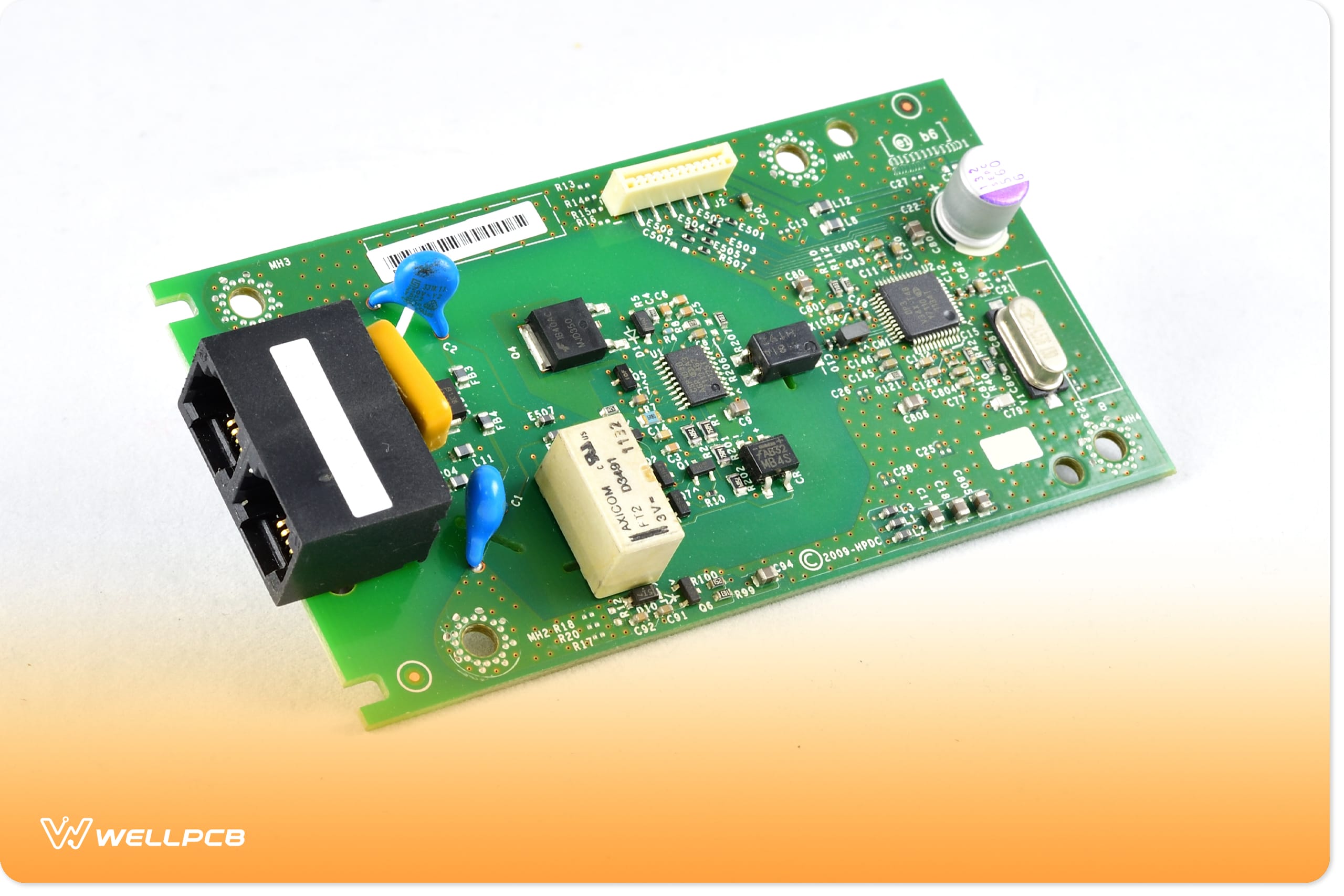
The TQFP (Thin Quad Flat Package) is a compact, low-profile version of the regular quad flat package. While regular QFPs can be as thick as 4.0 mm, TQFPs are significantly thinner, with a maximum thickness of just 1.4 mm.
This reduced thickness makes TQFPs ideal for designs where space and portability are critical, such as compact PCBs used in portable electronics and miniature devices.
What is an LQFP?
The LQFP (Low-Profile Quad Flat Package) is another low-profile version of the regular quad flat package. LQFP also has a maximum thickness of 1.4 mm and is designed for surface mount technology (SMT), meaning it is soldered directly onto the PCB surface without through-holes.
A key difference between the two is that LQFPs have gull-wing leads extending from all four sides. These longer leads improve ease of soldering and assembly, making LQFPs ideal for high-lead-count applications and boards requiring robust mechanical connections.
TQFP vs. LQFP: Key Differences
TQFP Specifications
- Lead Count Range: 32 to 176
- Body Size Range: 5 mm x 5 mm to 20 mm x 20 mm
- Maximum Package Height: 1.4 mm
- Lead Frame Types: Copper lead frames
- Available Lead Pitches: 0.4 mm, 0.5 mm, 0.65 mm, 0.8 mm, 1.0 mm
TQFP Applications
TQFPs are widely used in applications where compact size and reliable connectivity are essential. Common applications include:
- Microcontrollers
- Application-specific integrated circuits (ASICs)
- Power management integrated circuit (PMIC) controllers
- Gate arrays (FPGA/PLD)
- Video and audio systems
- Computing devices
- Communications boards
- Ethernet interfaces
- Integrated Services Digital Network (ISDN)
- Chipsets for tablets and laptops
- Telecommunications equipment
- Data acquisition systems
LQFP Specifications
- Lead Count Range: 32 to 208
- Body Size Range: 7 mm x 7 mm to 28 mm x 28 mm
- Maximum Package Height: 1.4 mm
- Lead Frame Types: Copper Lead Frames
- Available Lead Pitch: 0.4 mm, 0.5 mm, 0.65 mm, 0.8 mm, 1.0 mm
LQFP Applications
LQFPs are widely used in applications that require reliable connectivity and higher pin counts, including:
- Video and audio processing
- Graphics cards
- Virtual reality
- Chipsets for computers and tablets
- Telecommunications
- Disc readers and writers
- Communications boards

QFN vs. QFP
While this guide focuses on TQFP vs. LQFP, it’s worth understanding how QFPs differ from Quad Flat No-Leads (QFNs).
- QFPs use protruding pins to connect to PCBs.
- QFNs lack visible pins and connect to PCBs via exposed pads.
The absence of pins makes QFNs smaller, which is ideal for compact PCBs with limited space.
How Does a Thin Quad Flat Package (TQFP) Work?
The Thin Quad Flat Package (TQFP) is a slim, low-profile version of a QFP. Like all IC packages, it performs three critical functions: housing the silicon die, protecting the die from physical and environmental damage, and connecting the die to a larger circuit board.
The TQFP’s thinner profile makes it especially suitable for compact applications, such as single-board computers and microcontrollers.
What Industry Problems Does the TQFP Address?
The TQFP addresses two primary challenges in the electronics industry:
- Die Shrinking: As semiconductors become smaller, they require more compact packaging. The TQFP can accommodate these smaller dies without sacrificing performance.
- Space Limitations: With its low-profile design, TQFP enables the design of portable, condensed devices such as tablets and wearables.
What Are the Benefits of a TQFP?
TQFPs offer several advantages for manufacturers and designers:
- Cost-Effective Production: TQFPs require less material, reducing overall manufacturing costs.
- Environmentally Friendly: Most TQFPs comply with ROHS standards, using lead-free and sustainable materials.
- Reliability: With lead counts ranging from 32 to 176, TQFPs provide excellent mechanical reliability when soldered correctly.
What Are the Limitations of TQFPs?
Despite their benefits, TQFPs nevertheless present some challenges.
- Smaller Pitch Sizes: Higher pin counts result in narrower spacing between leads, which increases the risk of solder bridges.
- Fragile Pins: Shorter pins are delicate and prone to bending or damage if mishandled.
- Soldering Challenges: The small pin size makes manual soldering difficult.
To overcome these challenges, manufacturers often use pick-and-place machines for precise assembly.
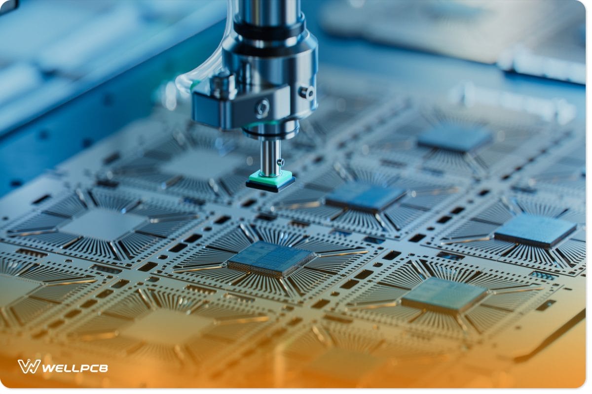
Benefits of TQFP’s Surface Mount Technology (SMT)
TQFP packages are compatible with Surface Mount Technology (SMT), which simplifies assembly and enhances performance. By improving electromagnetic compatibility (EC), SMT ensures components function reliably even in dense, high-speed circuits. SMT also streamlines manufacturing, reducing assembly time and enabling compact, lightweight designs.
How Gate Arrays Address TQFP Spacing Limitations
Gate Arrays help manufacturers address spacing limitations by increasing pin counts and ensuring stable connections. Field-Programmable Gate Arrays (FPGAs), for instance, are reconfigurable chips that allow manufacturers to maximize pin counts in TQFPs and optimize PCB connections.
What Is the Difference Between a TQFP and a Small Outline Integrated Circuit (SOIC)?
While both TQFPs and small outline integrated circuits (SOICs) are surface-mounted IC packages, they differ in lead configurations:
- TQFP: Pins extend from all four sides of the package.
- SOIC: Pins are only positioned on two opposite sides, making SOIC more suitable for simpler designs with fewer connections.

What Are the Different Types of QFPs?
In addition to TQFPs and LQFPs, other types of QFP are available. These include:
- Bumpered Quad Flat Package (BQFP)
- BQFP with Heat Spreader (BQFPH)
- Ceramic Quad Flat Package (CQFP)
- Plastic Enhanced Quad Flat Package (EQFP)
- Fine Pitch Quad Flat Package (FQFP)
- Metric Quad Flat Package (MQFP)
- Near Chip-Scale Quad Flat Package (NCQFP)
- Small Quad Flat Package (SQFP)
- Very Small Quad Flat Package (VQFP)
- Very Thin Quad Flat Package (VTQFP)
- Thin Dual Flat No-Lead Package (TDFN)
Costs Associated with TQFPs
The cost of manufacturing TQFP packages typically averages around $5 per unit, but several factors can influence this price:
- Pin count: Higher pin counts increase costs.
- Manufacturer location: (Costs vary between regions (e.g., U.S. vs. China).
- Handling and logistics: Packaging and shipping fees can add to the total expense.
TQFP vs. LQFP: Conclusion
Both TQFP and LQFP are reliable, cost-effective solutions for PCB design.
- TQFP: Ideal for compact designs requiring smaller packages, but demands more precise soldering due to shorter leads.
- LQFP: Easier to attach due to longer leads and better suited for applications requiring higher pin counts.
Despite their differences, both packages share key characteristics, including JEDEC Level 3 moisture sensitivity, which ensures reliable performance under controlled environmental conditions.
Need help with PCB fabrication or design? Contact us today for expert guidance.