Contents
What is a Transistor?
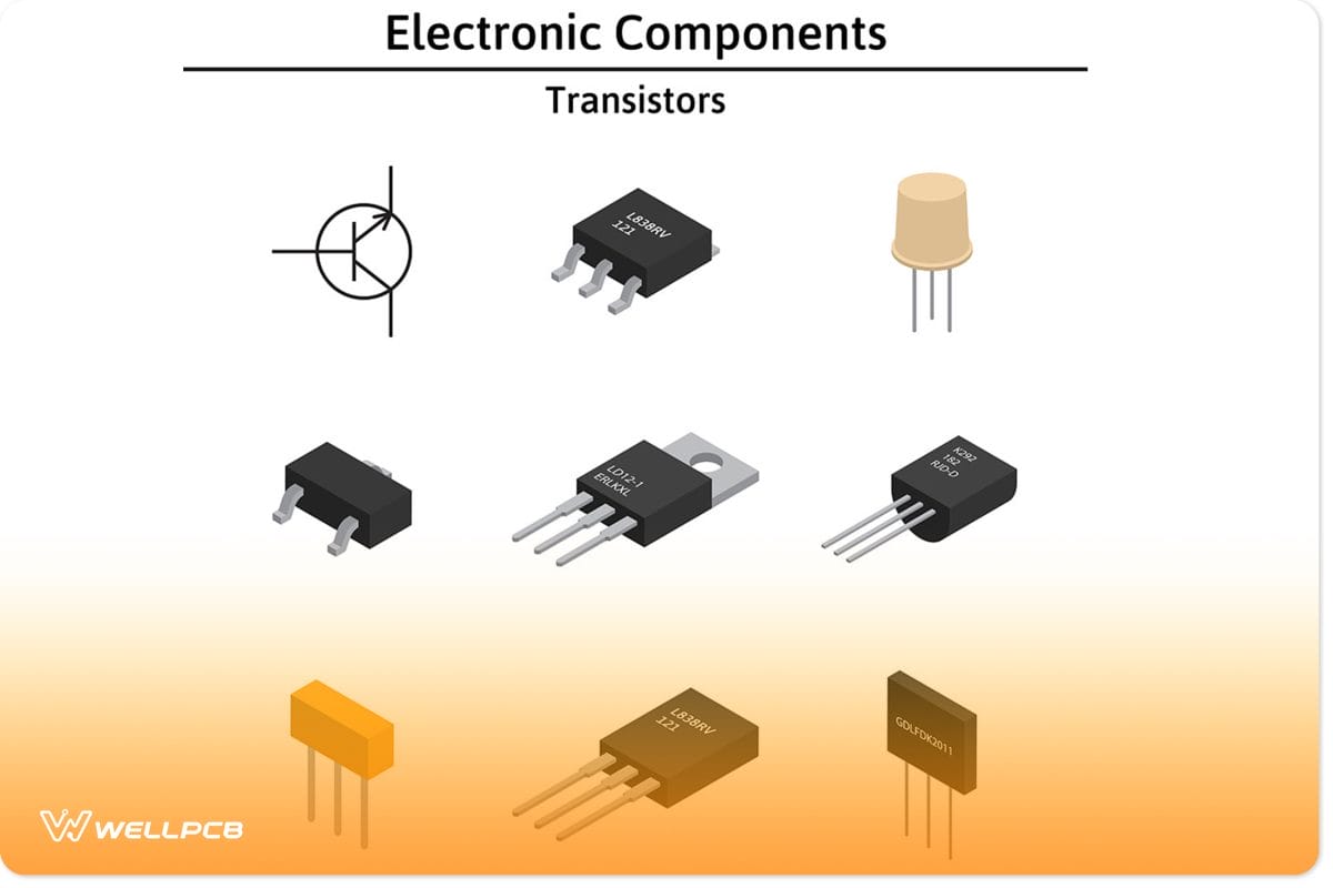
Transistors
Transistors are one of the most significant inventions of the last century. The name “transistor” is a portmanteau of the words Transistor vs Resistor. It is an electronic component found in various circuits, and we use it to amplify or switch electronic signals and electrical power. We mostly use transistors in integrated circuits. However, it’s not uncommon to attain them for use in an external circuit.
There are a variety of different transistors available on the market. Each transistor has its electronic symbol. The most common types of transistors are:
- Bipolar Junction Transistors (BJT)
- Field Effect Transistor (FET)
- Unijunction Transistor (UJT)
Much like LEDs, transistors are semiconductor devices. As such, they commonly comprise silicon. However, a small percentage may comprise germanium, too.
How Do Transistors Work?
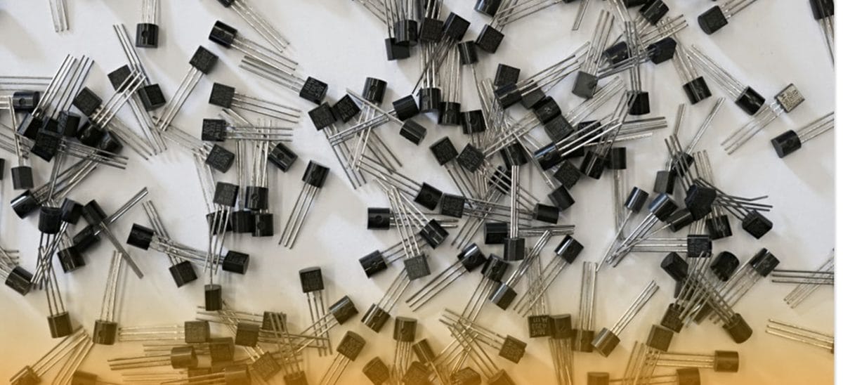
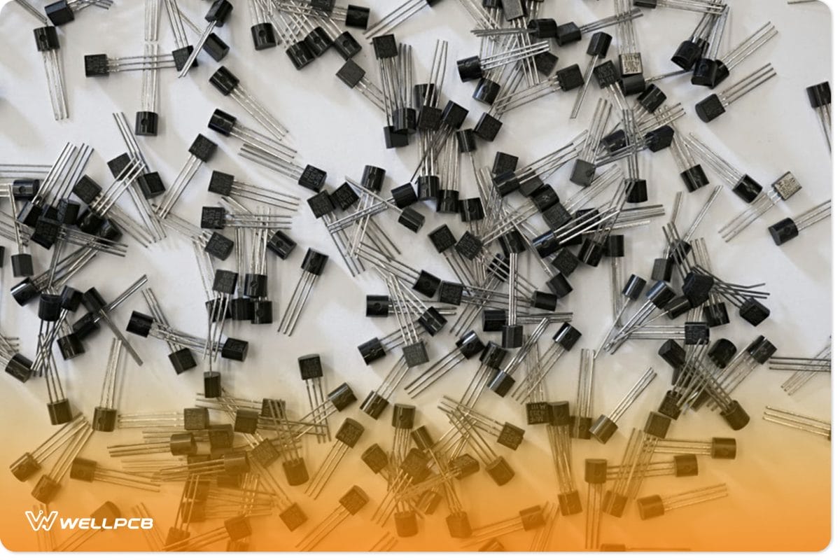
Collection of transistors
While there are many different types of transistors, in this section of the guide, we will focus on bipolar junction transistors since they are one of the most common. There are generally two types of bipolar junction transistors – NPN and PNP. Accordingly, each type has its electronic symbol.
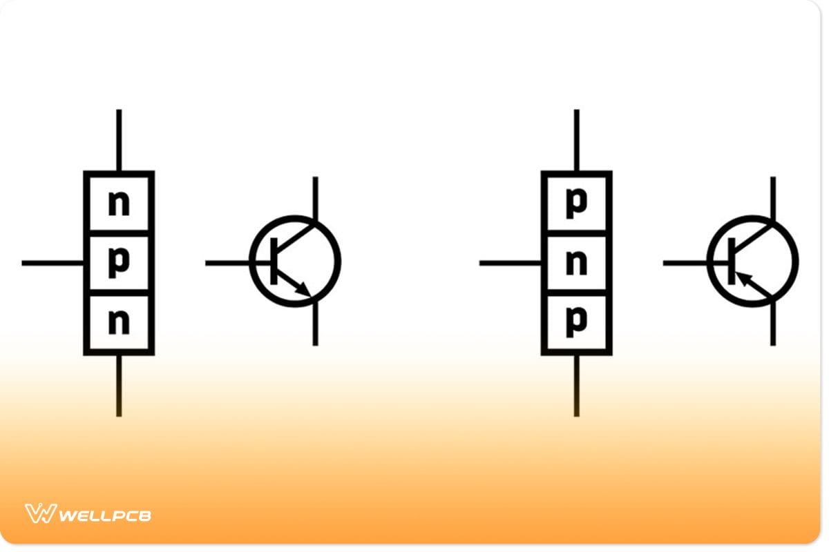
n–p–n and p–n–p bipolar junction transistor
Changing the semiconductor device properties of the transistor is the first stage of making it. We do this by introducing impurities into the structure. The name of this conduction change process is doping. The P portions are more positive in an NPN or PNP transistor, while the N portions are more negative.
From the above illustration, you should tell that each part of a BJT connects to a terminal. In fact, each terminal has a name to illustrate its function.
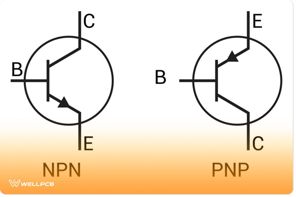
NPN and PNP transistor symbol
The names are Emitter(E), Base(E) and Collector(C). In a transistor symbol, the arrow is always part of the Emitter/Base connection. You can identify the type (NPN or PNP) of the transistor by where the arrows are pointing. An NPN requires a positive voltage to the base, while the PNP requires a negative voltage. This is because we dope NPN transistors with a negative charge while we dope PNP transistors with a positive charge.
Doping doesn’t only involve the addition of electrons. It also involves the removal or absence of electrons.
Functions of a Transistor
One of the transistor’s core functions is amplification. It can take a small voltage and convert it into a larger one. Additionally, it can also perform a transfer of resistance and act as a simple switch. Consequently, this makes it very useful in industrial applications.
The switch part of the transistor sits between the collector and the emitter. Altering the voltage between the base and the emitter is what activates or deactivates the switch. For instance, if the input voltage is 0V, the switch will open, and the output voltage will most likely be +10V. However, if the input is +10V, the switch will close, the effective resistance will be zero, and the output will be 0V.
What is a Resistor?
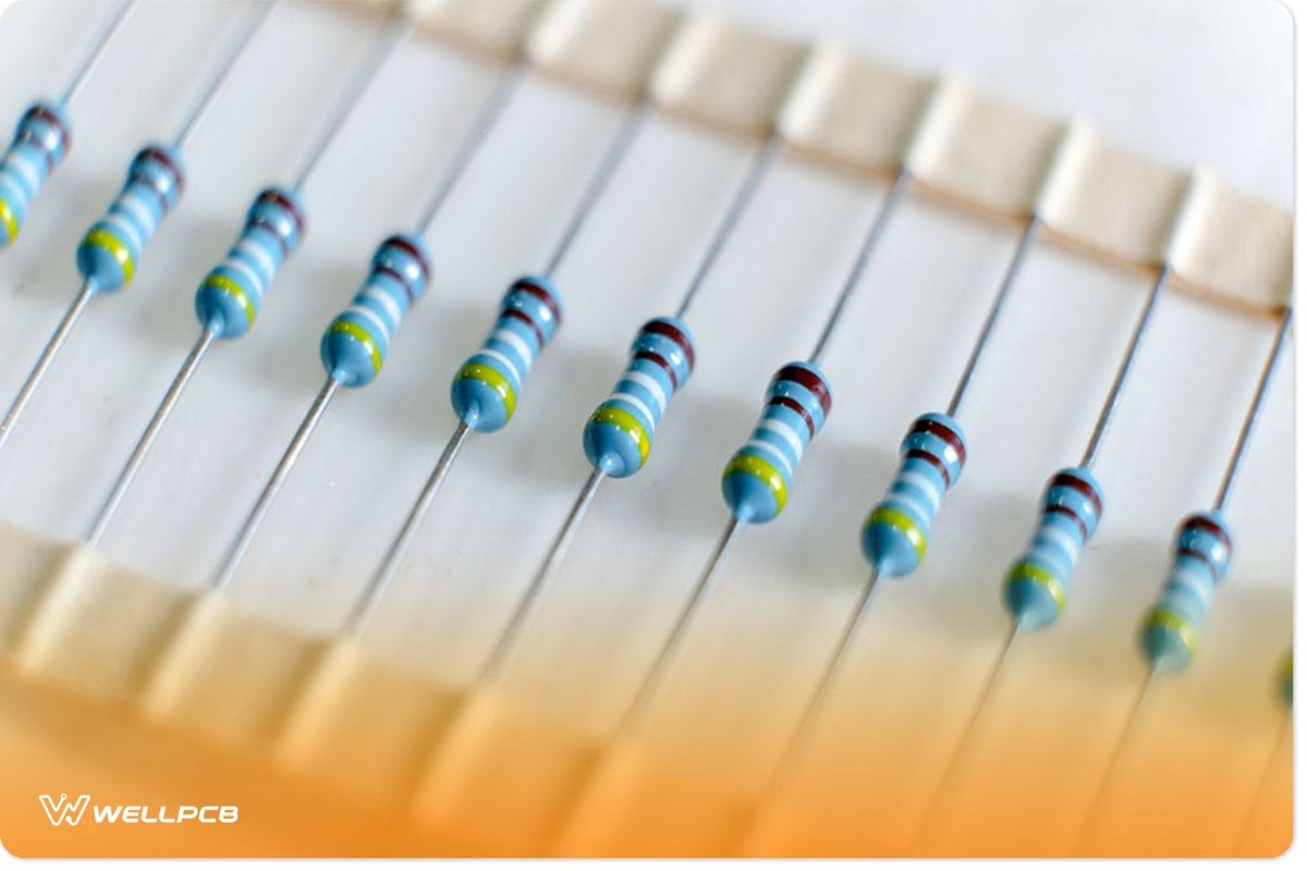
blue resistors in a row
Resistors are one of the most widespread electronic components. We use them on various electronic devices. To understand resistors, we must first understand what conductors are. Any substance that allows electricity to flow through it is what we know as a conductor. Some materials conduct electricity better than others – such as metals.
Inversely, some materials are not good at passing electricity. As such, these materials will struggle against the electrical flow and create resistance. Thus, the higher the effective resistance value of a material, the less current or electric charge will flow through it.
We use these insulating or non-conductive materials to make resistors. Generally, a resistor is a passive component with two pins.
Because most resistors are passive, the orientation we place in an electronic circuit has no impact on their efficacy.
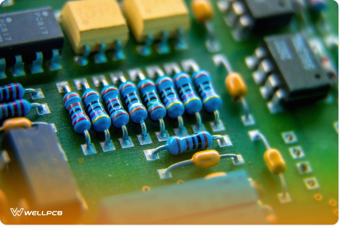
Resistors on PCB
In short, the purpose of the resistors is to resist the current flow in an electronic circuit. Additionally, we can also use them to adjust the intensity of signals and divide voltages.
Electrical resistance is a measurement that shows us how difficult or easily electrical current can pass through a conductor. We measure this initial resistance in what we call Ohms.
Thus, we can understand the differences between Transistors and Resistors by looking at the above explanations. While resistors and conductors may be opposites, Transistor vs Resistor is not. In fact, transistors are a mix between conductors and resistors.
But resistors can have degrees of resistance. In fact, some resistors allow you to adjust the amount of resistance they have. These are known as variable resistors. But how do they differ from transistors? We will cover that in the next section.
What is the Difference Between Variable Resistors and Transistors?
What is a Variable Resistor?
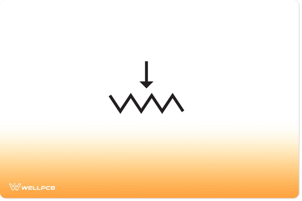
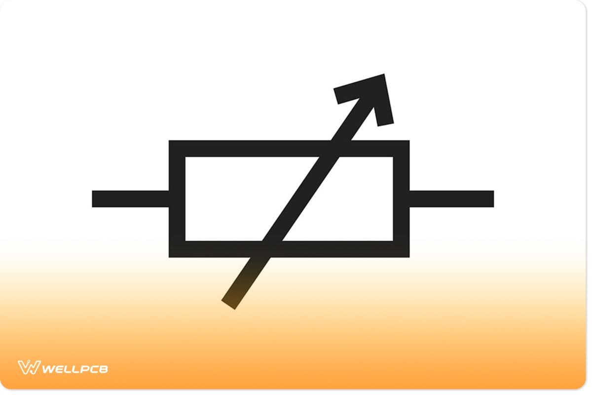
A resistor’s core function is to obstruct the current flow in an electronic circuit and create a voltage drop. As the name suggests, a variable resistor can change the level at which it obstructs current flow. The electronic symbol for the variable resistor is a rectangle/box with a diagonal arrow running through it.
variable transistor symbol
A variable transistor consists of a path and two terminals.
Differences Between Transistor and Variable Resistor by Working Principle?
Variable resistor
What you should remember is that a resistor is a linear device. Inversely, transistors are non-linear components. This may be obvious to tell from their functions. A transistor can act as both a switch (resistor) and an amplifier. Inversely, a resistor has one core function.
However, a key similarity between the variable resistor and the transistor is that the resistance between the collector current and emitter current is variable.
Envision a simple circuit that consists of a single bulb, battery, and a variable resistor. As you turn the control or slide on the resistor, you’ll either increase or decrease the intensity of the output current to the bulb. The bulb will either get dimmer as you increase resistance or brighten as you decrease it.
Transistor vs Resistor–Differences in Uses
There are three different types of variable resistors – potentiometer, trimpot, and rheostat. In principle, they all work similarly with a few differences. To understand the key differences between transistors and variable resistors, we need to explore where and how we use variable resistors.
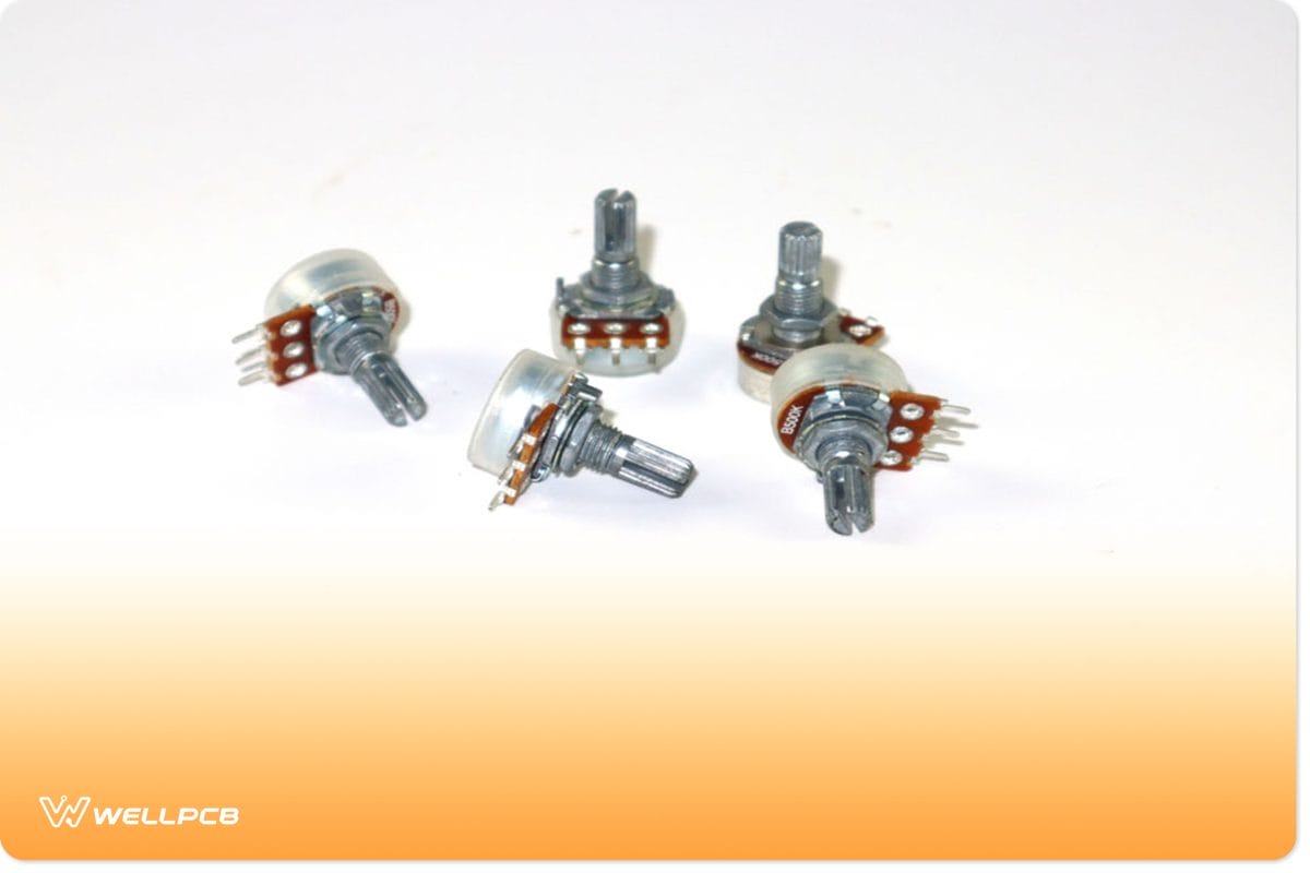
Potentiometer: What Is It and How Do We Use It?
Potentiometer icon in electronic circuits
A potentiometer is a common tri-terminal variable resistor. The potentiometer has three different connecting points (terminals). They consist of a dial or slide that allows you to alter the resistance between two connections. The connection points allow for various configurations.
For instance, you can connect your electronic circuit to the second terminal (input) and third terminal (output). This will allow you to use it as an ordinary variable resistor. However, you can connect all three terminals and use the potentiometer as a voltage divider, too. We often use potentiometers in circuits as dimmers for LEDs or other bright light sources.
Trimpot: What Is It and How Do We Use It?
Trimpot in white background
You may hear someone refer to potentiometers as pots. A trimpot is a more condensed version of a potentiometer. Hence its name – trimpot (trimmer potentiometer). You may also refer to them as pre-set resistors. You will need a screwdriver to adjust the resistance on them since they are smaller.
There are several different types of trimpots with different mounting options. You can also get them in a variety of adjusting orientations. For instance, you can have a trimpot with a top adjusting orientation with SMD mounting. Furthermore, you can find them as either single-turn or multi-turn types. Single-turn trimpots are the most cost-effective, while multi-turn trimpots give you a higher resolution.
Rheostat: What Is It and How Do We Use It?
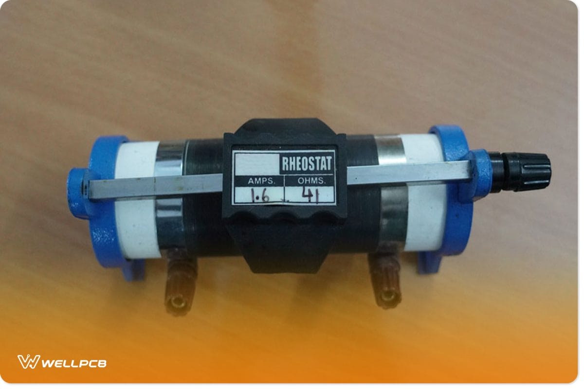
A Rheostat
Rheostats are the most common variable resistors. Unlike potentiometers and trimpots, they only have two terminals/pins. However, we use the rheostat in many of the same applications. We use it to control current, dim incident light sources, or control motors connected to an electrical circuit. Rheostats look nothing like potentiometers. They carry their adjustment knobs on the side.
Types of Transistors and Their Uses
Transistors function much in the same way variable resistors do. The difference is that you can control the resistance of a transistor by applying current. As such, we often use transistors in conjunction with a pull-up resistor or pull-down resistor. Inversely, variable resistors require manual analog switching. Nevertheless, some applications for transistors include:
- Phototransistors can convert light pulses into digital electrical signals. They’re handy for security systems, readers, infrared detectors, and lighting controls.
- Bipolar junction transistors can function as switches, filters, rectifiers, oscillators, and amplifiers. As such, we incorporate them into cell phones, TV sets, and radio transmitters.
- Field-effect transistors can amplify weak signals. They are cheap to manufacture. We use them in testing equipment such as voltmeters and oscilloscopes.
- Darlington transistors have high electric current gains. They are so sensitive that they can pick up current from small hairs. As such, we use them in small devices such as driver chips and push-sensitive buttons.
- Multi-emitter transistors are special bipolar transistors we use in NAND logic gates.
Conclusion
If you have reached this point of the guide, you should understand Transistor vs Resistor. It would help if you also understood how transistors differ from variable transistors in function and use. We hope you found this guide to be useful. As always, thank you for reading.