Contents
What Is A Varistor?
A varistor is a term in the electrical world that combines two words: variable and resistor. You can also call the two-terminal semiconductor device a VDR (voltage-dependent resistor).
The VDR name is because the device helps to protect electronic devices from overvoltage transients. In other words, its resistance tends to change spontaneously based on the change in voltage across the device.
So, when the varistor’s voltage increases, resistance decreases. And there’s a drastic drop in resistance when there’s an excess increase in voltage.
Since the varistor helps to protect circuits from any voltage surge or fluctuations, it’s vital to place it in a shunt with the protected device. The varistor is similar to the diode because of its nonlinear, non-ohmic current-voltage feature. But it differs from the diode as it has identical features for its directions (left and right sides) of traversing voltage.
Initially, engineers constructed varistors traditionally by combining two rectifiers like germanium-oxide or copper-oxide rectifiers. And they did the combination in the antiparallel configuration. But these days, engineers use combined ceramic metal-oxide materials.
These materials are adequate for displaying directional behavior at a microscopic scale. Hence, you can call the device MOV (metal oxide varistor). Further, examples of varistors are the rheostat and potentiometer.
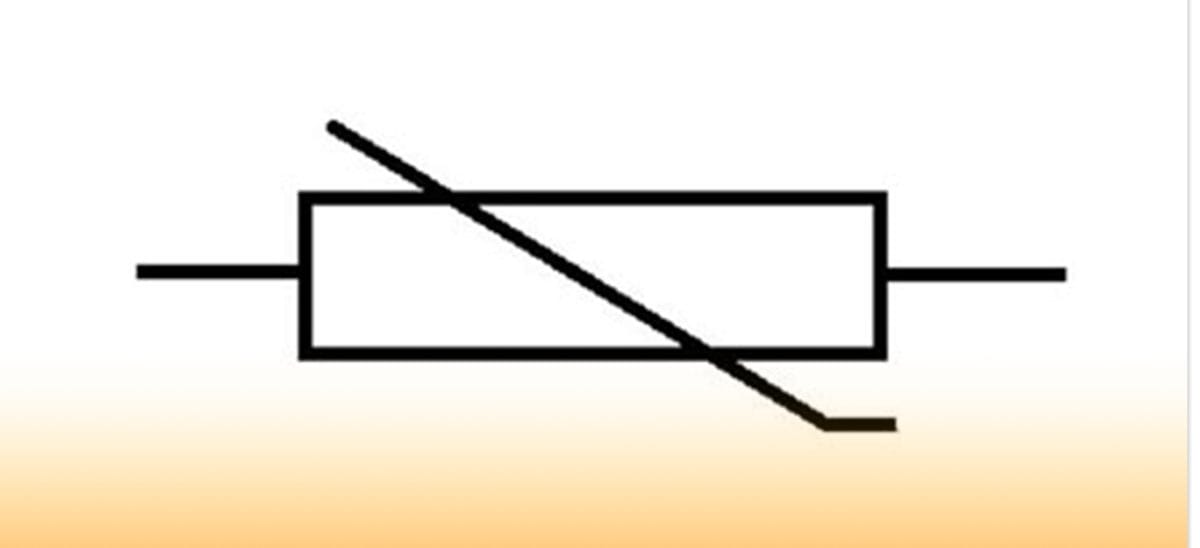
Varistor Symbols
Varistor Icon
As we mentioned earlier, the varistor symbol is a circuit representation with a small added section on one end of a diagonal line that crosses a rectangle—which is the resistor’s body. Plus, the picture shows that the nature of the varistor is nonlinear.
No doubt, you may come across other symbols representing the varistor on different occasions. But this one is widely used and sustained under common standards.
What are The Characteristics Of a Varistor?
When you have a voltage-dependent resistor, you should expect a varying nonlinear resistance. And this usually depends on the voltage you apply. That said, when there are normal load conditions, the impedance tends to be high.
However, the impedance decreases to a low value—if the voltage threshold exceeds. Also, when you subject a circuit to a high voltage transient, the varistor will swing into action by conducting and camping the transient voltage. And the goal is to ensure that the transient voltage attains a safe level.
In addition, the varistor protects the circuit effectively by partially absorbing and conducting the energy from the incoming surge.
The metal oxide varistor appears to be the most common type of varistor. If you’re familiar with the diode junction, you notice that the varistor’s grain boundaries offer P-N junction semiconductor features. And you can construct the device with a merged matric of zinc oxide grains.
Also, you can compare the extensive network of diodes in parallel and series to the matrix of erratically oriented grains. Further, when you expose MOVs to repeated surges, it tends to degrade. That is, the clamping voltage of MOVs decreases a bit after each wave. And the level of decrease depends on the relationship between the joule rating of the MOV and pulse.
In addition, you can experience a possible failure mode if the clamping voltage keeps decreasing. And this could cause a fire hazard. So, the best way to avoid this situation is by connecting the MOV in series with a thermal fuse. That way, the device can disconnect if overheating occurs.
But to minimize degradation altogether, it’s crucial to limit exposure to surges by using a high clamping voltage that matches what the protected circuit will allow.
How Do Varistors Work?
The working principle of a varistor is straightforward. But it’s crucial to understand the concept behind voltage surges and how they exist in a system. First off, it’s vital to note that most spikes are switching.
With that in mind, you can say that a high voltage surge could happen when you switch off an inductive circuit. And the wave exists because of the instant release of energy that the inductance stored. There’s a rule that says, “when you switch off surge, it doubles the voltage.” Also, when you switch on the surge, it results in a double current.
So, a varistor offers high voltages, a low resistance path, and low voltages a high resistance path. That said, you can also see the variation in resistance with voltage from the varistor’s static resistance curve. The curve also displays a nonlinear nature that doesn’t follow Ohm’s law.
In other words, when you apply a small voltage across the electrode, it’s only a minute current that flows. In contrast, when you use a large voltage, you’ll notice a breakdown. And this happens due to reverse leakage via the diode junctions.
The breakdown usually happens because of electron tunneling and thermionic emission that initiates substantial current flow. As a result, you’ll notice a nonlinear current-voltage characteristic.
That said, you can show the connection between voltage and current by:
I = k. Va
Where:
- I – current
- V – voltage
- a – degree of nonlinearity
Varistor Types
The major types of varistors available include:
1. Metal oxide varistor—previously discussed this type as a nonlinear transient suppressor variant that comprises zinc oxide in a matrix of other metal oxides like manganese, cobalt, and bismuth between two metal plates.
2. Silicon carbide varistor—a variant that dominated the markets before MOVs came along. It comprises silicon carbide. Plus, they were helpful in high voltage applications.
But it has a significant snag which is drawing a considerable standby current. Hence, you’ll need to use a series gap to reduce the standby power consumption.
Varistor Applications
From everything you’ve read here, it’s easy to tell that varistors are sensitive devices to voltage change. And they have some snags. For instance, varistors don’t offer protection from voltage sags, current surges during a devices’ startup, or current during a short circuit.
But the advantages outweigh the drawbacks. For example, they are fast over-voltage devices as well. Also, you can use the bipolar devices for both DC and AC supplies. So, it’s not surprising that manufacturers use them to suppress the lighting of industrial equipment and mains borne transient from domestic appliances.
The varistors are helpful in the following applications:
- Microprocessor protection
- Industrial high energy AC protection
- Electronic equipment protection
Electronic backup protection fuse
- Car electronics protection

Circuit protection device for cars
- Low voltage board level protection
- Power supply protection

UPS power protection
- Transient voltage surge suppressor

Transient voltage surge suppressor diode
- Telephone and other communication line protection
- Surge protector power strips
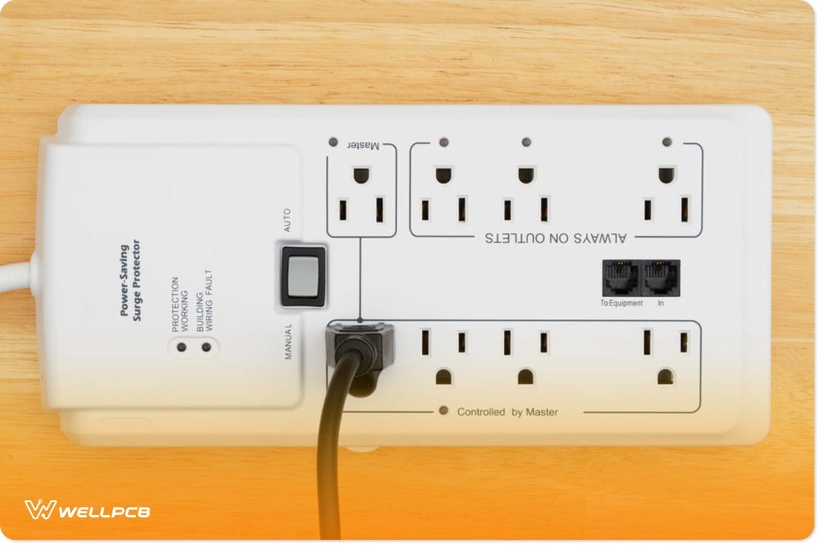
Power source surge protector
- Cable TV system surge protectors
- Radio communication equipment transient suppression

Man with radio communication
Varistor Testing
You can quickly test a varistor with a multimeter. The process starts when you turn the multimeter on and ensure that you set it correctly. That is, the device should read resistance times 1000 ohms. Then, you can touch a one-meter probe at the free varistor lead while the second probe stays connected.
Once you finish that step, take note of the resistance on the meter. If the resistance is relatively low, it means that the varistor is terrible. But, if the resistance reads nearly infinite, it means that the varistor is in good condition.
At this point, you can remove the lead and fix a new varistor of the same rating if the previous one is bad. However, if the varistor is good, solder the lead you disconnected again.
Also, it’s vital to note that varistors are in different categories based on the voltage range they can endure without damage. Other factors you should look out for in a varistor includes:
- Operating voltage
- Maximum current
- Energy rating (joules)
- Breakdown voltage
Closing Words
Most times, it’s impossible to avoid events that come with a great magnitude of energy, like a lightning strike. But you can save yourself from the implication of the event with varistors—as they help overturn line voltage surges. And it’s a good reason why a lot of appliances ranging from domestic to industrial use varistors.
If you plan to embark on this project, it’s vital to be familiar with the varistor symbol—which shows the non-linear nature of the semiconductor device.
What do you think about varistors? Have you tried infusing them into your electronic projects? Or do you need more clarity on the topic? We’ll be more than happy to help. Please feel free to contact us.