
Contents
Voice Changer Circuit Concept
What’s fascinating about the uniqueness of human beings is being able to have different voice tones. Consequently, should we make a call, it would be easy to figure out who we are conversing with, thanks to the interlocutor. Moreover, even without seeing a speaking individual, it is easy to fish them out of a crowd due to their voice.
However, for this experimental project, we will use a digital voice changer circuit that has a designation of changing the timbre of an individual’s voice to a different one. Further, it can be modified to sound like an alien or a robot voice.
We have borrowed the voice modulator technology from the device HOLTEK. HOLTEK is a voice changer chip that often processes the voice signal it has been fed digitally at the moment.

(Sound change software in the mobile phone)
How HOLTEK works
- First, it shifts the spectrum’s frequency that associates with the voice in question, downwards or upwards, in seven sequential increment steps.
- Then, you will hear a relatively thicker or thinner frequency at the resultant output.
- Finally, you can compare the results you have obtained to a playback speed with a piece of vocal information that you had initially recorded on a tape while decreasing or increasing frequencies.
An exception factor with HOLTEK is that it doesn’t affect or distort the speech’s speed in the comparison process. Furthermore, it can add two special sound effects to the sample speech you’ve tested: robot and vibrato. The robot effect makes the human speech more robot-sounding, whereas vibrato brings the tremulous sound effect to the voice.
To add to the concept, both voice outputs go to the IC via a standard electret microphone, and then you’ll receive the dimensioned output signal on a dynamic speaker.
Generally, the whole HOLTEK system operates on a supply voltage of a 9V battery.
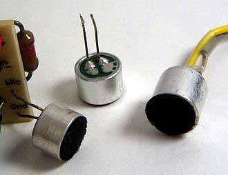
(electret microphone)
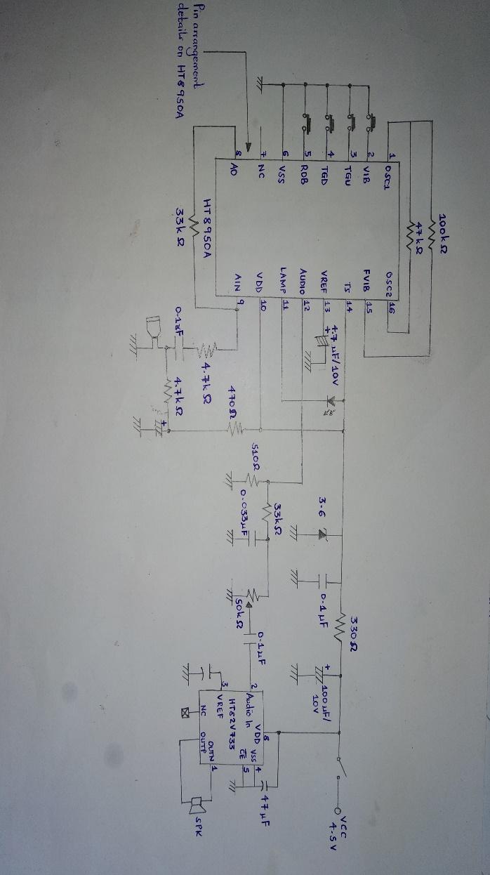
Voice Changer Circuit Schematic
Circuit schematic
The below circuit diagram shows the circuit of a voice changer circuit that you can build from an HT 8950 datasheet. All you will need to do is use a different compatible amplifier circuit that you require, then replace it with the existing audio amplifier.
Working Principle Introduction
Besides having a functional amplifier block with an internal polarization microphone, an HT8950 also has a D/A converter of 8 bits, a static RAM (also known as SRAM), and an A/D with 8 bits.
D/A and A/D operate on an 8Khz sampling rate. The rate can not only cover a human’s voice spectrum of about 3Khz, but it can also produce a better speaker output quality and a highly desirable signal-to-noise ratio (SNR)
How do we build a Voice Changer Circuit?
- Parts List
They include;
Capacitors
C4, C6, C7 – 220uF/ 16V, electrolytic,
C3, C5 – 0.1uF (104), ceramic,
C2 – 0,47uF (474), ceramic, and
C1 – 4,7 uF/ 16 V electrolytic.

(Close-up of various types of capacitors)
Semiconductors
SPK1 – speaker 8 / 0.25 W,
Transducers MIC1 – electret microphone with a miniature feature,
Zener diode D1 – 6, 2V / 0.5W
IC2 – LM386 audio amplifier, and
Integrated Circuits Modulator voice IC1- HT8950A.
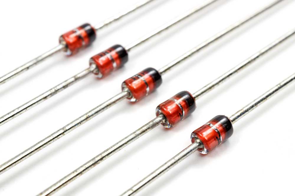
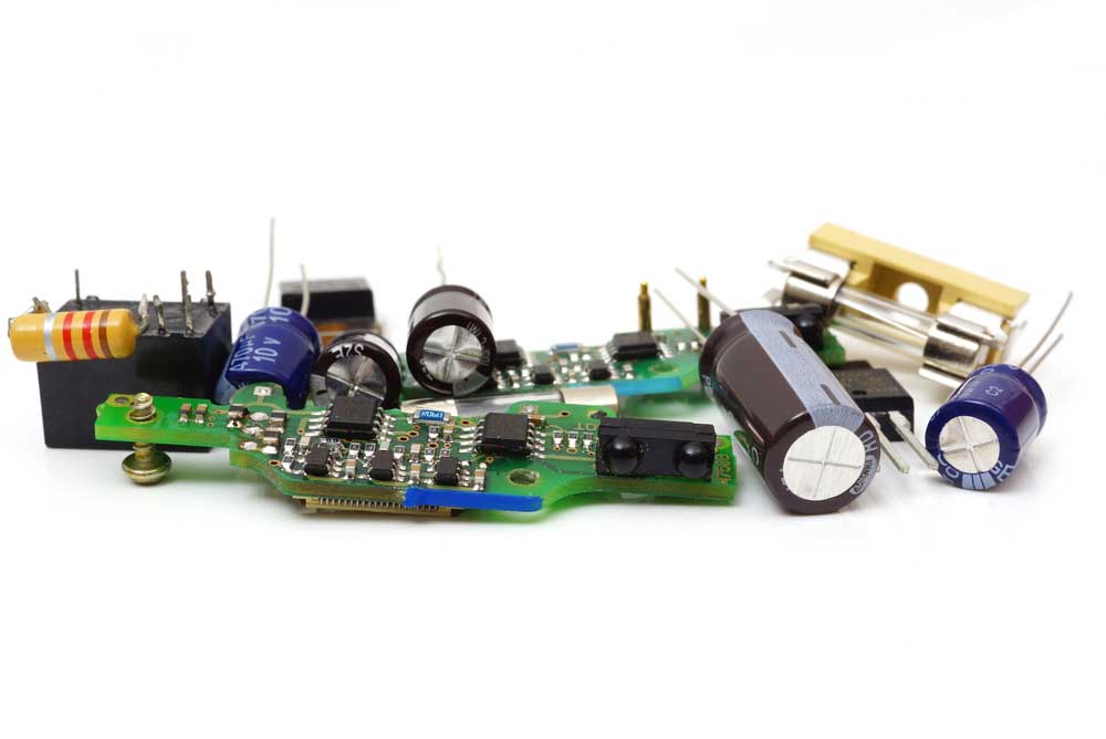
(Zener diode)
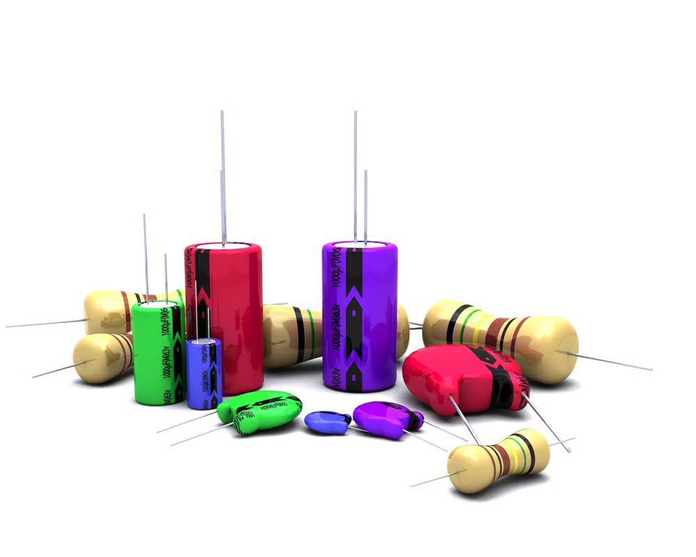
(Capacitors and semiconductors)
Electromechanical
S1 to S4 – push-button switches miniature NAJ1–type connector for a 9V battery snap.
Resistance (1/4W 5%)
R9 – 5K, trimmer, one lap,
R8 – 8,2K,
R7 – 470,
R4, R5, R6 – 4,7K,
R3 – 39K,
R2 – 47K, AND
R1 – 100K.
Schematic diagram of the voice converter and its operation
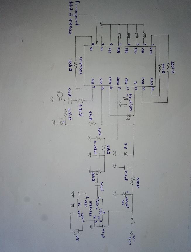
The circuit will operate as follows;
- It starts with the microphone capturing the voice signal, and through the R4 C2 network, it transfers it to the internal amplifier HT8950. Here, the open-loop amplifier will gain a voltage of approximately 2000.
- Secondly, capacitors C4, R7, and R5 provide the electret element in their biasing conditions. Normally, the injected HT8950 will have a limited yet amplified bandwidth time. Thus, it sends voice signals to the A/D bits, whereby internal 8 has a digitized sampling rate of about 8 kHz.
- Then, the oscillator controls the sampling signal generator that produces the stipulated time base.
- Often, R2 determines the frequency of the oscillator (about 512Khz).
- Next, SRAM will store the digitized voice signal. Afterward, a control circuit will remove the information from the static RAM and then transfer it to another latching register.
- Further, information as a speech signal goes to the D/A converter from the register, where it transforms back to its original analog form. You can then extract the signal on pin 12 – AUDIO output.
- The original signal from the D/A converter may or may not have an offset frequency spectrum depending on the transfer speed from SRAM to D/A. Step by push-button switches S3 (DOWN) and S2 (UP) determine the condition. In other words, as you touch the system, you will move the S3 step down and S2 at a step-up situation in a cycle.
- Finally, the speech signal in its analog form passes through the C3 R8- network and then reaches the LM386 (IC2) amplifier. Consequently, the amplifier guides the SPK1 speaker and enables its audibility.
(PCB production workbench)
Build the circuit on a PCB board
- You can use a double-sided PCB measuring 3.2 x 2.5 inches.
(Double-sided PCB example diagram)
- Incorporate test points in the PCB. For example, you can have TP2 follow through the signal going to the power- amp from the register and T1 follow through the signal from a microphone.
- Thirdly, use IC sockets, then solder the chips onto the design board. Fortunately, you can keep replacing the chips to note the difference in their activities.
- Often, you will find jumper JP, R7 that is the volume control, and microphone jack J1 mounted on the board. However, for the DIY project to work, you need to replace the board-mounted components with panel-mounted ones and then connect them back to the PCB using hook wires. For example, use a switch in place of JP.
(type of a mini-microphone jack )
Pin detailed information
The pin arrangement includes the following;
VREF – reference voltage internal amplifier 14,
AUDIO – audio output 13,
LED – lamp output for volume 12,
VDD – positive power line 11,
AIN – input of the internal amplifier 10,
AO – output internal amplifier9,
NC – not connected 8,
VSS – negative supply line/ GND 7,
ROB – input selector mode step ROBOT 6,
TGD – input selector step DOWN 5,
TGU – step input selector UP 4,
VIB input mode selector vibrato3,
OSC1 input of oscillator 2.
- Test
- Before proceeding with switching on the power, use alcohol and a soft-bristled toothbrush to clean the board. Then, as always, look out for lacking components, bad solder joints, false value capacitors, wrong IC in a socket, broken copper traces, etc.
- Next up, measure the input resistance starting from positive to ground. A low or zero resistance could mean a short circuit that you need to trace.
- In the third step, set your volume low, then plug an electret microphone into the J1, attach the headphone/loudspeaker, and finally, to TB1, add 12V. Confirm if the LED is working.
- Lastly, gradually speak into your microphone while also increasing the volume to your desired level. If the circuit is amplifying in the process, remove the jumper and ensure your voice is undergoing modulation.
(PCB test)
Summary
To conclude, you can use a voice changer circuit to alter a human’s voice by programming the sound that appears at the microphone input to a different one. For instance, you can edit the voice to sound like a robot. Whichever the project, following through the diagrams and simple steps will surely give you a superb result. In case of any concerns, however, you are free to contact us at any time.


