It’s not great when water spoils that circuit you’ve been working on for some time. And, it’s even more frustrating when it hurts a device that needs protection from water or rain. Luckily, we have a solution. The water sensor circuit is all you need. A water sensor circuit is also a fun project you can build to help protect your devices from water damage. So, in this article, we’ll show you how a water sensor circuit works, its diagram and components, several applications, and most importantly, how to build an easy water sensor circuit.
Are you ready? Let’s jump in!
Contents
How Does a Water Sensor Work?
A water sensor is an easy circuit, and it’s simply a solid-state switch that can activate when it detects the presence of water. It’s also a circuit capable of loads operated by ac mains.
So, how does this easy circuit work? Though there are different variations of the water sensor, they all have one thing in common.
Plus, water detectors will detect when there’s water in places there shouldn’t be water. Or when there’s a water leak.
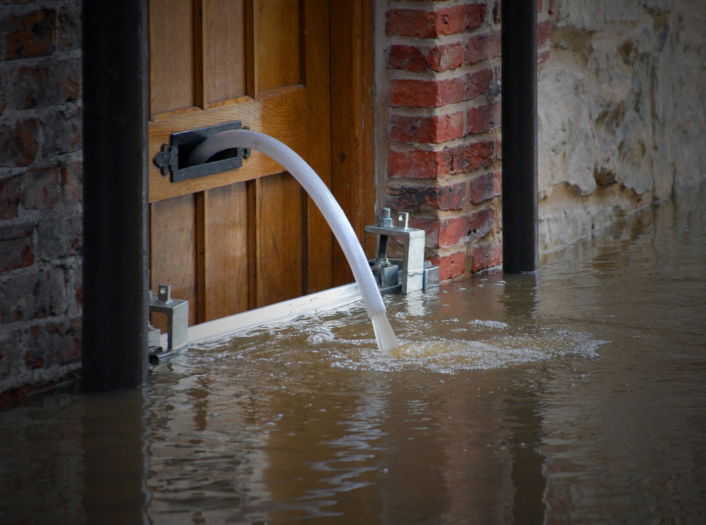
Water Damage
So, when you place a water sensor in places or devices that shouldn’t leak or have water on them, the water sensor will alert you either through sound or indication.
Some sensors may even send you a notification if it has access to Wi-Fi. The water sensor will always make sure your devices stay safe from water damage.
Water Sensor Circuit
So, in this section, we’ll discuss four different ways to build a water sensor circuit.
Simple Water Sensor using a Breadboard
For this circuit, we used a transistor as a switch because water is a good electricity conductor. So, water can work as a trigger to turn on the transistor.
Schematics
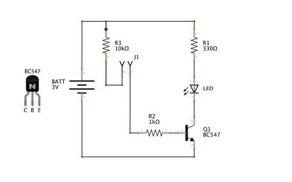
Simple Water Sensor Circuit Diagram
Source: Wikimedia Commons
For this circuit, an NPN transistor turns the LED indicator on/off. Plus, the course also features two probe points (jumper wires). So, we connected one wire to the transistor’s base via a current limiting resistor. For the second wire, we connected it to the positive supply voltage via another current limiting resistor.
Thus, when both jumper wires touch water, it turns on the transistor and creates the signal by turning on the LED indicator.
Components
- NPN transistor (1)
- Resistors (10k and 1k ratings) (2)
- LED (1)
- Breadboard (1)
- power source battery (3 volts preferably) (1)
- Jumper wires
Steps
The first thing you should do is gather your materials and tools. Once you have your materials ready, install your components according to the illustration below:
Breadboard Diagram
Source: Wikimedia Commons
For better understanding, connect one end of your jumper wire to the NPN transistor’s base and connect the second one to the positive terminal of your power supply voltage.
Remember to connect these jumper wires through current limiting resistors (R3 and R2).
Note: the R3 is a current limiting resistor to prevent damage if you wrongly connect the jumper wire to the negative terminal instead of the positive.
Thus, the 10k value prevents the current from going above a low 0.3 mA value.
Additionally, this circuit proves you don’t need a complicated design to make something useful.
Water Sensor Circuit using a 555 Timer IC
Here’s another water sensor circuit or rain alarm circuit that you can use on any device you want to protect from rain or water. The 555 timer for this circuit works in astable mode. Plus, the emitter current released from the BC548 transistor is what drives the 555 timer IC.
Whenever the probes of this circuit detect wetness, it switches on the transistor and allows some current to flow between the emitter and the base.
On the other hand, if the probes don’t sense moisture, the transistor will not turn ON.
555 Timer IC Water Sensor Circuit
Source: Wikimedia Commons
Here’s how this circuit works: first, when you switch on the supply, the 555 timer’s output pin voltage will be 0v.
Thus, the transistor will be in the OFF position since the current from the emitter is low. Furthermore, The VCC (pin 9) of the 555 timers and the transistor’s collector are connected.
Hence, the transistor will not supply any current to the 555 timers when switched off.
However, when the probes detect moisture, the transistor starts conducting and supplies the current required for the 555 timers to operate.
Since it’s in astable mode, it produces sound via the output pulses of pin3. Additionally, pin 3 is also responsible for driving the loudspeaker.
Also, you can control when the transistor conducts through an on/off state switch. Plus, this circuit doesn’t need a base resistor because the transistor has a switch mode. Thus, the oscillator circuit or emitter impedance serves as a current limiter.
Components
- 555 timer IC (1)
- Capacitor (1)
- LED (1)
- Resistor (1)
- Speaker (1)
- Transistor (BC548) (1)
Steps
The water sensor circuit using a 555 timer IC is also easy to build. All you have to do is assemble your circuit components on a PCB of good quality.
Also, make your probes out of insulated copper aluminum wires. You can use non-reactive metals for examinations as an alternative.
Finally, ensure you place your probes correctly and at places where they can detect water easily.
Water Sensor Circuit using Arduino
Now here’s a circuit that’s different from the rest. Here, you’ll connect your already made water sensor or a water sensor brick.
When you connect an Arduino to your water sensor, it offers an efficient way to sense floods, leakage, spills, and even rain.
You can also use this circuit to sense the volume, presence, or level of water.
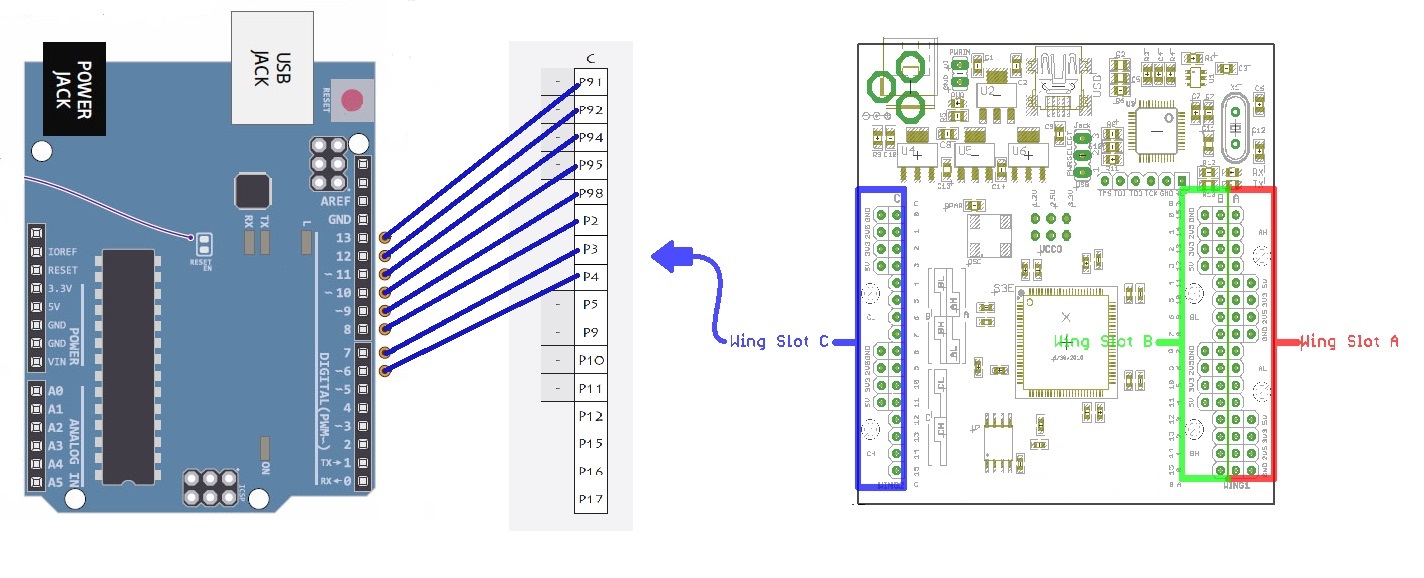
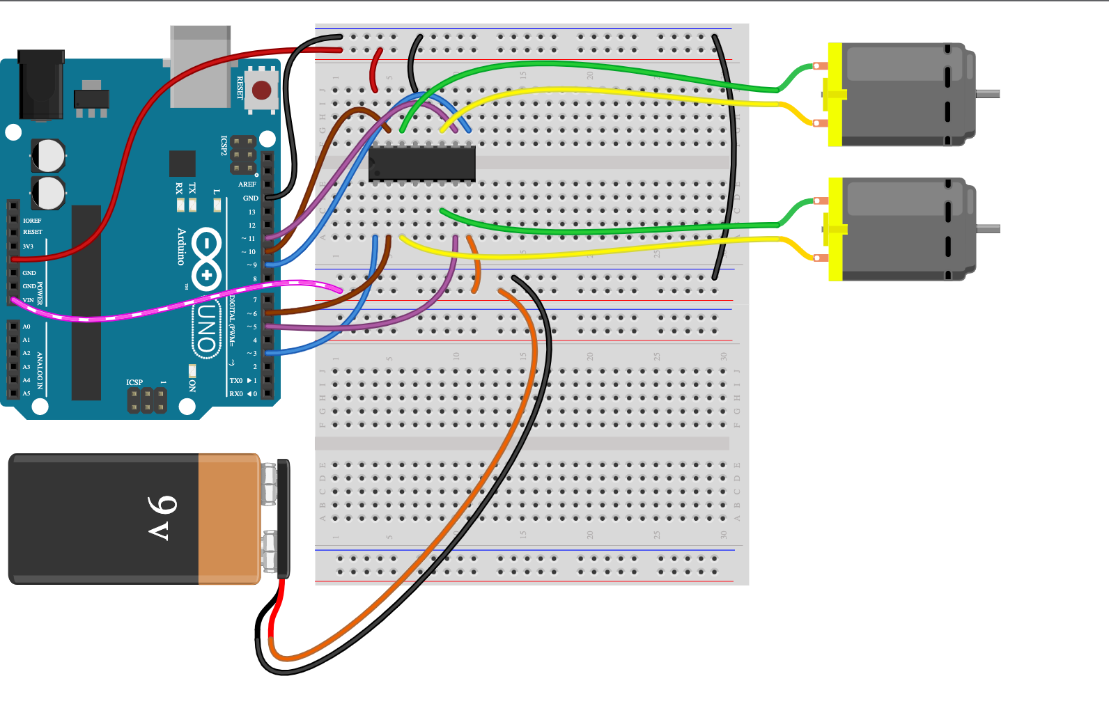
Arduino Schematic
Source: Wikimedia Commons
For this circuit, we connected the water sensor to the Arduino’s digital pin 8. Also, we used an LED to serve as an indicator for when the sensor detects water.
Components
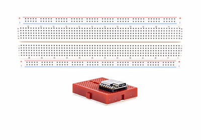
- Breadboard (1)
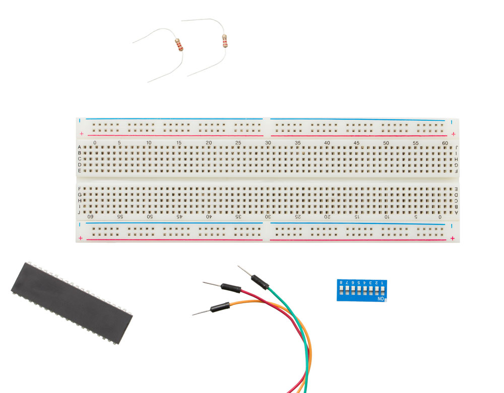
Breadboard
- Water sensor (1)
- LED (1)
- Arduino Uno R3 (1)
- Resistor (330 Ohm) (1)
Steps
All you have to do is follow the above schematics and connect your components to your breadboard accordingly for the circuit assembly.
Next, it’s time to code. Open your Arduino software to code in the Arduino language and have complete control of your circuit. Here’s the code you should use:
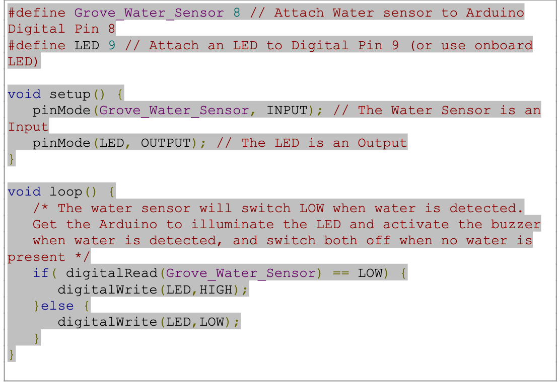
Also, it would help if you connected the terminals of your water sensor to the Arduino board. There are three terminals on a water sensor: S, Vout(+), and GND (-). So, here’s how you should connect them:
- Connect the LED terminal to digital pin 9
- Then, join the +Vs terminal to the +5v terminal
- Afterward, join the S terminal to the digital pin 8
- Finally, merge the GND terminal to the Arduino GND

Applications of Water Sensor Circuit
Water sensors work in areas or devices where there’s a possibility of water damage. So, here are some places you should use a water sensor:
- Dishwashers
- Sinks
- Washing machines
- Fish tanks

- Hot-water heaters
- Refrigerators with water dispensers
- Boilers
Summing Up
Water damage often leads to considerable losses in homes and offices.
Plus, in a world where we have many water-sensitive devices, the damage can sometimes be unrepairable.
However, water sensors help prevent injuries and avoid loss of properties.
Usually, you can find water sensors in most home improvement stores, both local and online.
However, if you can’t purchase one, this article provides several ways to create a water sensor circuit that suits your purpose.
That sums up this article; if you have any questions, feel free to contact us. We’re always happy to help.


