The critical focus of electronics/electrical engineering is to control and manipulate electronic signals. We have discovered various methods to harness and influence the flow of electricity. One of these methods is pulse width modulation. If you have interacted with DC motor controllers, you have likely come across this term before. Nevertheless, the following guide will answer the question: What is Pulse Width Modulation (PWM)? It will cover how PWM works, its advantages and disadvantages, and its applications.
Contents
What is PWM, and How Does It Work?
PWM has many different uses. It grants us minute control over other devices. The easiest way to picture PWM in action is by using a circuit with a LED.
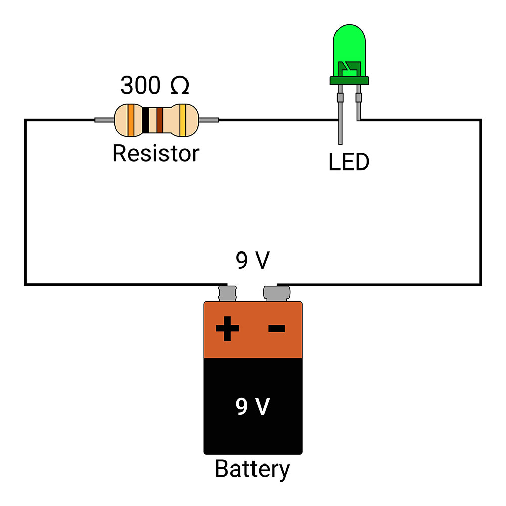
LED Circuit
You can pulse power through the LED by switching the power on and off at a specific frequency, rhythm, or pulse width. In this instance, PWM allows you to dictate the brightness of the light source – whether it be a standard light bulb or LED. Additionally, you can use PWM to control the speed of motors. Hence, its use in DC motor controllers. Nevertheless, the creation of switch-mode power supplies is another notable application for PWM. This type of power supply earns its name from how it uses the PWM technique.
PWM Signal Generation
PWM dispatches signals at short, quick intervals instead of a continuous stream. This allows us to control the intensity of the movement we send to each component in a circuit. How do we create consistent PWM signals without manually opening and closing a switch?
One of the most effective ways to do this is using a comparator. You may have come across these devices while working with voltage monitoring circuits. The comparator receives two input signals. One is the modulating signal, and the other is a non-sine wave (AKA Sawtooth Wave or Non-Sinusoidal Wave).
Next, the comparator compares these signals before outputting a PWM signal. If the non-sinusoidal movement is greater than the modulating signal, it will produce a modulated pulse signal in a high state. Ultimately, the size of the sawtooth signal will determine the width of the resulting modulated pulse signal.
Usually, we measure PWM signals using duty cycle, frequency, and pulse width. People often mix these terms up. Each time has a unique meaning and represents a different measurement of the PWM signal. All these metrics are time-based.
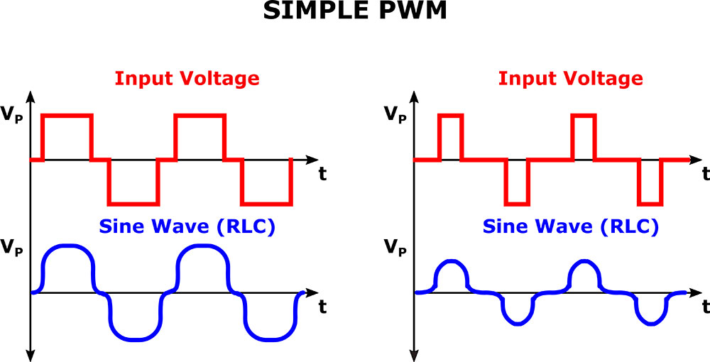
Diagram of Simple PWM
PWM TON and TOFF
Because PWM essentially pulsates signals, the resulting waveform can have two states. TON describes the on time, i.e., when the movement is high. Inversely, TOFF refers to the off time, i.e., the interval when the signal is low.
PWM Period
The period describes the length of time of a single pulsation, i.e., when the sum of TON and TOFF.
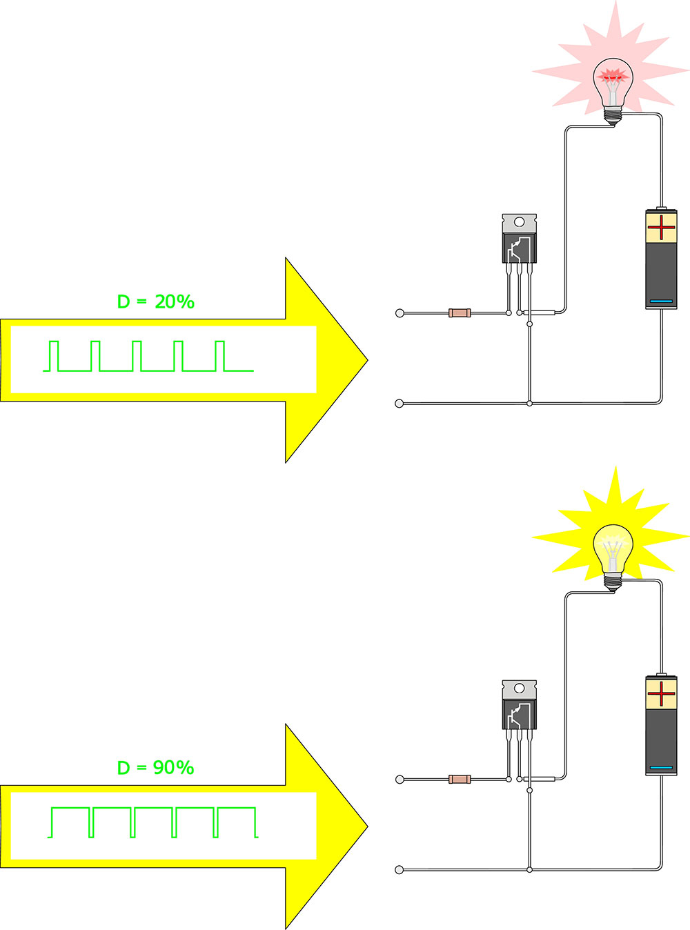
PWM Duty Cycle
The duty cycle describes the time the signal remains in a high/on state compared to the time it takes to complete a single period. Commonly, we use either ratios or percentages to represent it.
A 50% duty cycle indicates a signal is equally on and off during a single process. Typically, this duty cycle would result in a square wave. A 100% duty cycle means the signal was always on during a single process and is unlikely to use PWM. Inversely, a 0% duty cycle indicates that the movement is always off during the revolution and, similarly to a 100% duty cycle, is unlikely to use PWM. It is important to note that we use the duty cycle to determine the time a signal is on a high (as opposed to when it is on low/off).
PWM Frequency
We represent frequency using Hertz (Hz). We use frequency to ascertain the speed at which a signal pulsates. Essentially, it measures how many (duty) cycles occur per second.
PWM Pulse Width
The pulse width represents the time when a signal was on. As such, we measure in time. – usually milliseconds.

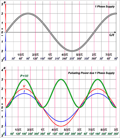
Sine and Square Waves in an Oscillator
Advantages and Disadvantages of PWM
Advantages:
- Ensures that motors generate peak torque despite running at lower speeds
- Prevents overheating of light sources and allows you to control their brightness
- Maintains a high input power factor.
Disadvantages:
- High PWM frequencies result in substantially higher switching losses
- It can cause radio frequency interference (RFI). This can be useful if you are building a radio frequency jammer.

PWM Applications
You can use Pulse Width Modulation for the following applications and scenarios:
Controlling the intensity and brightness of light sources
Motor Speed Controllers (voltage regulation)
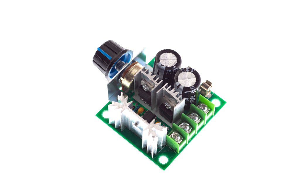
Motor Speed Controller
Power Supplies
Step-up
Step-down
Regulated
Frequency encoding in telecommunications
Audio and video signal amplifiers
More efficient cooling in computers (computer fans and other cooling solutions)

UPS
Testing Pulse Width Modulation Using Arduino
The best way to understand PWM is to see it in action. Incidentally, you can observe PWM using a microcontroller. Accordingly, you will need a microcontroller with at least two PWM pins. This section explores how to assemble a simple Arduino PWM project.
We recommend the Arduino Uno Rev 3. It has six PWM pins that can produce signals at varying frequencies. Arduino usually marks PWM pins on its microcontrollers using the tilde symbol (~).
Nevertheless, the following is a simple project. Thus, all you will need in addition to the Arduino microcontroller are:
- Generic LED
- 220Ω Resistor
- 10KΩ Single Turn Potentiometer (Optional)
- Generic Breadboard
- Jumper Wires (At Least Two)
Arduino’s code library features an analogWrite(Pin, value) function that allows you to generate PWM signals. Again, if you use an Arduino Uno, most of its pins will generate a maximum frequency of 490 Hz. Albeit, the PWM pin configurations for most Arduino microcontrollers are as follows:
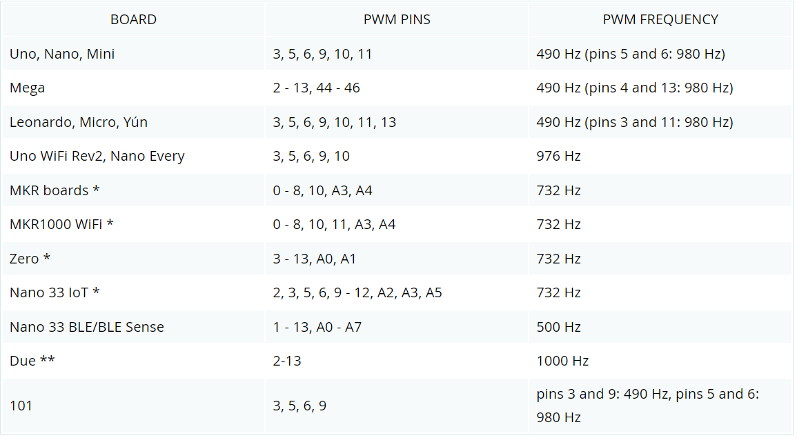
The analogWrite() method accepts two parameters, both integer types. Pin refers to the Arduino PIN you plan to output the signal. Accordingly, value refers to the duty cycle and can be a number between 0 (consistently low/off/0% duty cycle) and 255 (consistently high/on/100% duty cycle). A value of 127 will produce a signal with a duty cycle of 50%. Furthermore, each duty cycle has a corresponding output voltage level: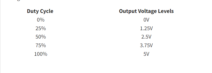
Assembly Instructions
The following instructions will use Arduino Uno Rev 3. However, you should be able to apply them to any PWM-enabled microcontrollers.
- Connect the LED’s positive terminal to the microcontroller’s 6th digital Pin.
- Next, connect one end of the resistor to the LED’s negative terminal.
- Finally, connect the resistor’s other end to the microcontroller’s ground pin.
Of course, we recommend making these connections through a breadboard. Your setup should look similar to this but with one connected LED:
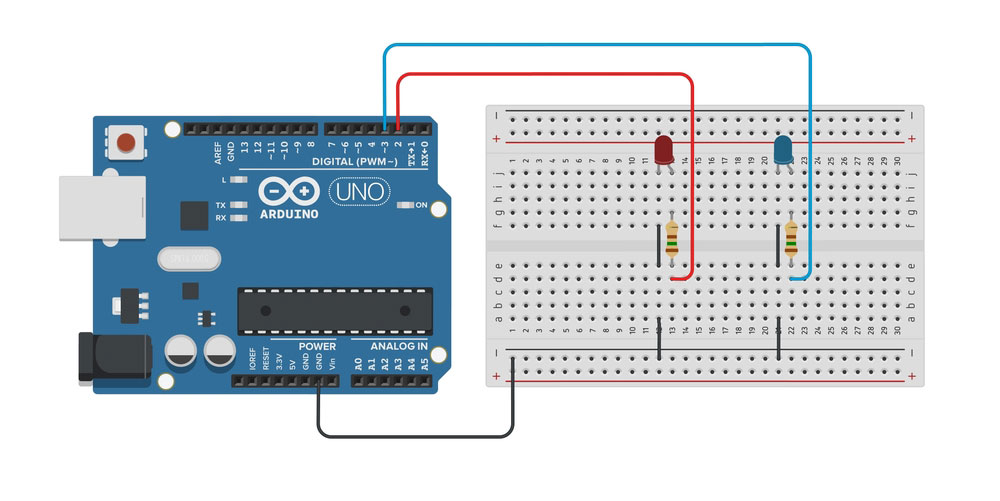
Arduino Blink Circuit
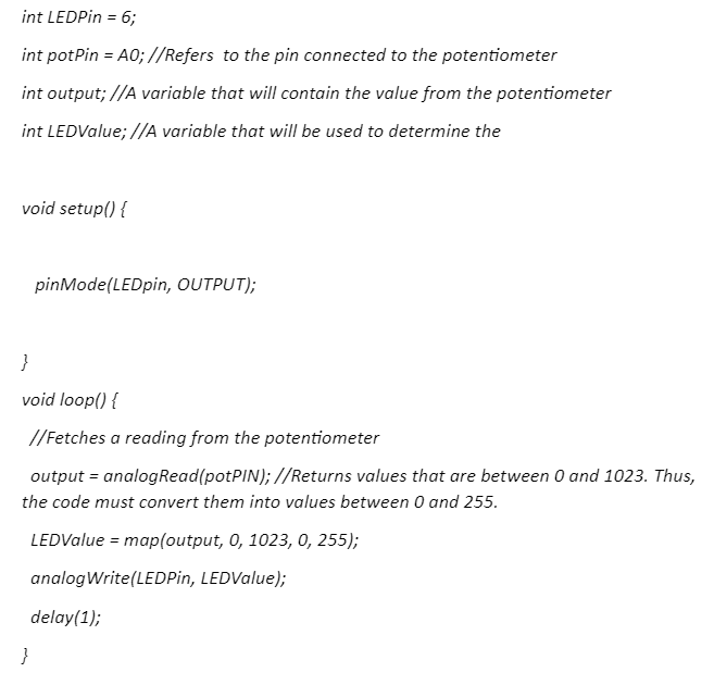
Arduino PWM IDE Code
Enter the following code into the Arduino IDE and flash it/upload it to your microcontroller:
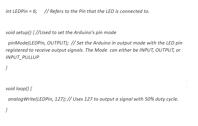
The above project shows you how to control the brightness of an LED using pulse width modulation through an Arduino Microcontroller. As you will be able to tell, the higher the duty cycle, the brighter your light source (LED): You can experiment and modify the above code in any way you want to.
Example of PWM
If you have a 10KΩ single-turn potentiometer, you can add it to your project and use it to control the brightness of the LED. However, it will require you to use the following code:
FAQs
Is PWM AC or DC?
PWM typically produces AC output voltage and frequencies. You can use transistors to convert DC into pulse-width modulated AC voltages.
Is PWM Digital or Analog?
PWM allows you to convert or encode analog signals into digital ones.
Does PWM change voltage or current?
PWM lowers the average current. In turn, this reduces the average power. However, it does not affect the peak voltage.
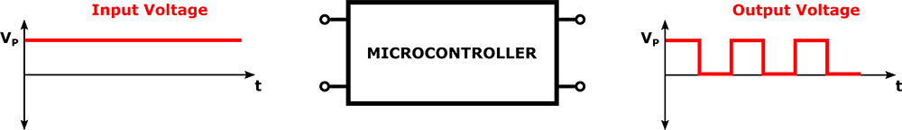
Diagram of Microcontroller Converting DC signal into PWM AC signal
Conclusion
The above guide explores what pulse width modulation is and its usefulness. It also investigated how to test PWM by building a simple LED dimming project using an Arduino microcontroller. However, this is not the only way you can use and observe PWM through an Arduino project. Arduino and its partners provide a wide range of accessories, such as fans and motors, that you can use to build your very own projects. Nevertheless, do not hesitate to contact us if you have any PCB or electronics-related questions. We are always happy to help.