Contents
What Is A 4047 IC?
The 4047 IC or the CD 4047 is a CMOS multivibrator. The options with this multivibrator can be either Low-power monostable or stable.
Additionally, a 4047 IC converts DC to AC mainly. It also generates sine and pulse waves.
The 4047 IC is one of the three multivibrators available today. In addition, this chip falls under the astable and monostable categories.
Nonetheless, this makes this multivibrator lacking in only one category. However, the category that the 4047 IC falls short of is the bistable multivibrator category.
A bistable multivibrator is where the circuit is stable in either state. Notwithstanding, an external trigger pulse can flip the state of the circuit.
However, the circuit is unstable in an astable multivibrator and continually switches from one state.
Generally, it functions more or less like a relaxation oscillator.
On the other hand, a monostable multivibrator has where only one state of the circuit is stable while the other is transient. In summary, a circuit with a monostable multivibrator is a one-shot circuit.
With all this in mind, it is good to point out that the voltage range of a 4047 IC is 3V to 18V. It, however, works best at 5V.
Pin Configuration
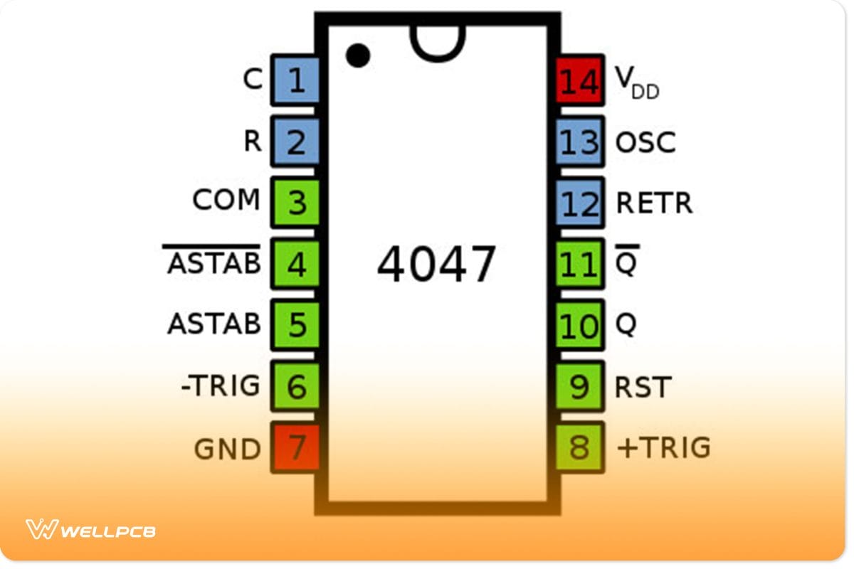
4047 IC Pin Configuration
| Pin Number | Pin Name | Pin Description |
| 1. | C | It is used to connect external capacitors. |
| 2. | R | It is used to connect external resistors. |
| 3. | RCC | Connects to resistors and capacitors. |
| 4. | AST’ (Astable Bar) | Low when used in Astable mode. |
| 5. | AST | High when used in Astable mode. |
| 6. | -Trigger | In Monostable mode, it gets High to low transitions. |
| 7. | VSS | Ground pin of IC. |
| 8. | +Trigger | The monostable mode uses it. It receives Low to High transitions. |
| 9. | EXT RESET | The monostable mode uses it. It receives Low to High transitions. |
| 10. | Q | Give standard high output. |
| 11. | Q’ | The inverse output of pin 10 means it gives low output. |
| 12. | Retrigger | In Monostable mode, it simultaneously uses retrigger +trigger and –trigger pin. |
| 13. | OSC Out | It gives oscillated output. |
| 14. | VDD | Positive input pin of IC. |
Features Of The 4047 IC
- The buffered outputs are accurate and complimented.
- It has consistent and symmetrical o/p characteristics.
- Its inputs are consequently buffered.
- It is tested 100% for quiescent current on 20V.
- It can operate in monostable and astable modes.
- A single capacitor and resistor are required externally.
- The 4047 IC has less power utilization.
- In general, it has high noise immunity.
- The parametric ratings are 5 Volts, 10 Volts, and 15 Volts.
Specifications Of The 4047 IC
- For any single input, the DC input current is ±10mA.
- Has an operating range of temperature ranges from -55°C to +125°C.
- A 4047 IC chip has an input supply range of 3V to 18V.
- The storage temperature range of the 4047 IC is -65°C to +150°C.
- Its soldering lead temperature is 260°C.
Difference Between 555 & CD4047
The 555, better known as the NE555 timer, is an integrated circuit used in timers. It is also popular in pulse generation, timers, and oscillator applications. From face value, the first difference you can see when you put a 555 and a CD4047 side by side is the number of pins.
A CD4047 has 14 pins, while the 555 has eight pins. These pins are available in PDIP, SOIC, and VSSOP packages generally. The pins on an NE555 in order from one to eight are namely:
- Ground
- Trigger
- Output
- Reset
- Control
- Threshold
- Discharge
- Power
Other equally important key differences between the 555 and the CD4047 include but are not limited to:
- Firstly, the maximum operating temperature of the 555 is between 0°C to 70°C. On the other hand, the CD4047 has an operating temperature of -55°C to +125°C.
- Secondly, the operating voltage of the CD4047 is between 3V to 18 V. While the 555 ranges from 5V to 18V.
- And lastly, a 555 circuit operates in bistable, monostable, and astable modes. Yet, on the other hand, the CD4047 only operates in monostable and astable modes.
NE555 Low Pass Chip
How To Build A CD4047 Astable Multivibrator Circuit?
Simple Square Wave Generator
A simple square-wave generator
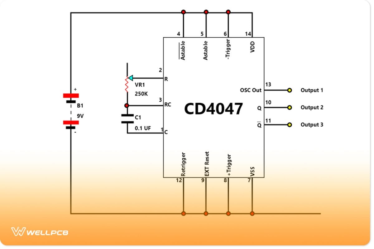
As an illustration, we will build a CD4047 astable multivibrator circuit. To illustrate this, we will create a simple square wave generator.
The source of power for our generator will be a 9-battery power supply in effect. With this, you will eventually create a square wave with three forms. Eventually, all these three outputs will have a 50% duty symmetrical cycle.
Requirements
- Breadboard of universal PCB board.
- Wires
- Batteries
- Potentiometer
- Semiconductor: CD4047
- 14 pin socket
How To Build
With everything ready, layout your breadboard accordingly, and connect everything properly. When doing this, be very careful with the wiring. While doing this, bear in mind the polarity of the electrolytic capacitor.
Subsequently, measure and record the waveform at pins 13, 10, and 11. In summary, C1’s value as per this arrangement is broken down. As a result, this will determine the frequency.
- 1uF = 1-10Hz
- 0.1uF = 10Hz-1kHz
- 0.01uF = 100Hz-10kHz
All the while, the VR1 potentiometer is 250K.
Results
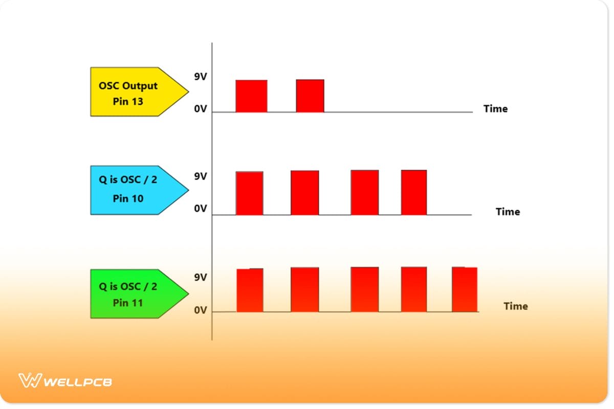
- Firstly, with a 50% duty cycle, pin 13 is the basic frequency obtained by VR1 and C1. The process is across pins 1, 2, and 3 generally.
- Concurrently, pins 10 and 11 both show the half frequency of the original frequency at pin 13.
- Lastly, the frequencies at pins 10 and 11 are inverted to each other’s phrases. Consequently, these inverted outputs are both 180 degrees out of phase.
In summary, here is a graphic interpretation of the wave for a signal of the three outputs.
An infographic displaying the interpretation of a wave
While you cannot adjust the 50% duty cycle, you can set the frequency output by adjusting VR1 and charging C1. Not to mention, 1K to 1M is the range value you get from VR1. C1, on the other hand, will determine the frequency.
When building this basic square wave, remember to pick a low leakage capacity. Doing this will reduce waveform distortion and an overall mistake frequency.
Blinking LEDs Using The CD4047
With this experiment, you will get a clearer picture of the use of the 4047 IC, as can be seen.
Requirements
- Breadboard or universal PCB board
- Wires
- Battery
- Resistors
- LEDs
- Potentiometer
- CD4047
How To Build
Without having to change much from the previous board in the first place, all you need to do is implement a couple of changes for the most part. Consequently, you need to add the LEDs and the resistors to your breadboard.
Test And Results
Therefore, with everything properly laid out, you can now try adjusting the VR1 and changing the C1. Consequently, doing this will allow you to notice the difference between the LEDs. As a result, you will have two blinking LEDs.
Other Experiments Involving Astable Multivibrators
- A 1KHz Oscillator circuit using CD4011 NAND Gates.
- A simple Square wave generator circuit with NOR Gate CD4001.
- 1KHz Oscillator using Schmitt trigger.
- A simple 1KHz clock generator circuit using CD4049 NOT Gates.
- A simple High-frequency Oscillator circuit using NOT Gate.
- Triangle wave generator circuit.
Applications
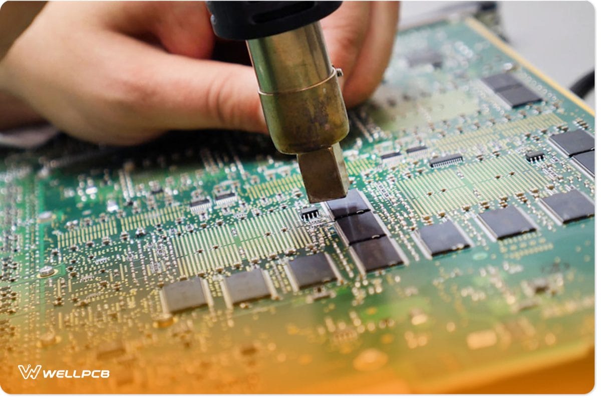
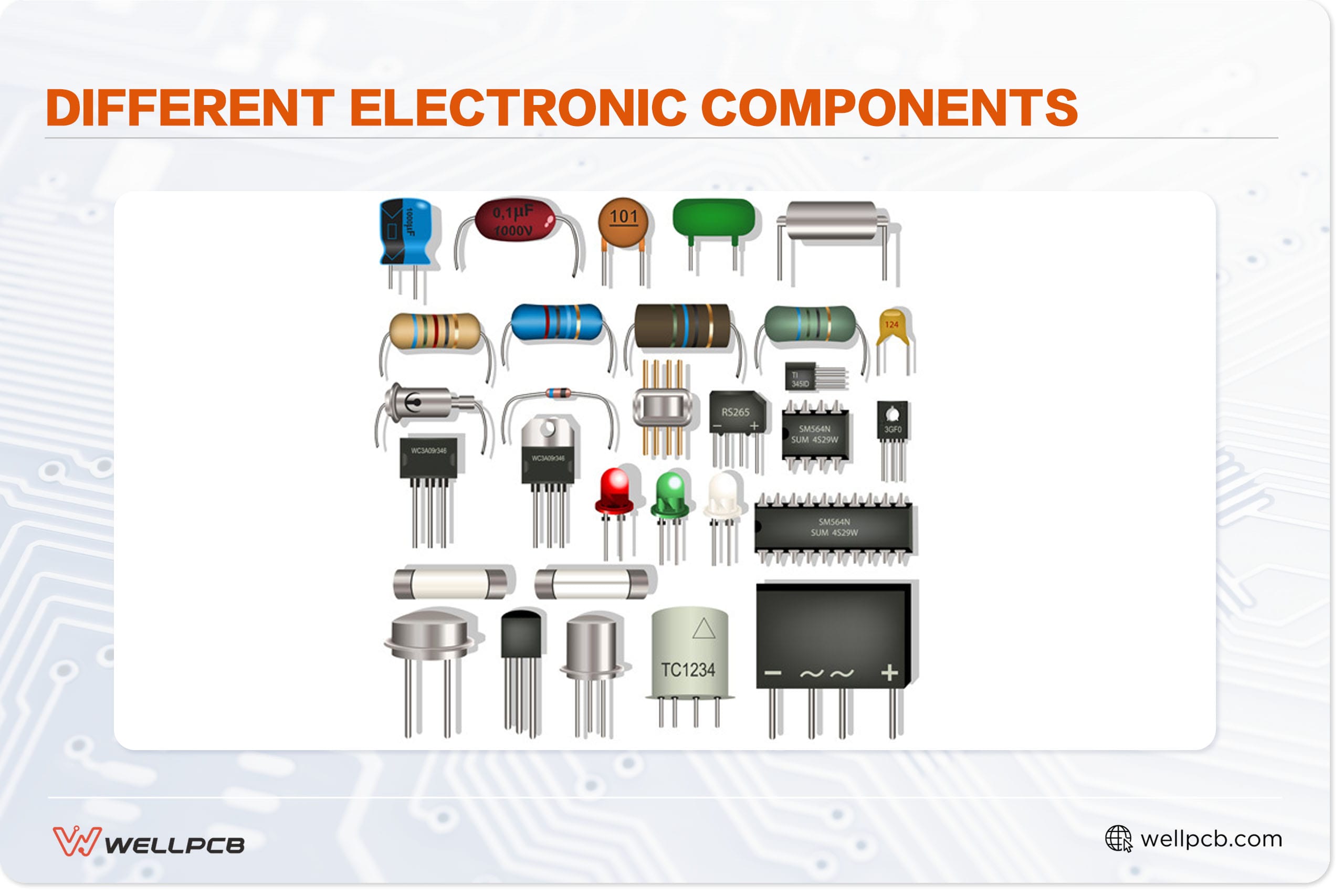
Electronic circuit board with integrated chips
- Envelope detection
- Used for frequency discriminators
- Frequency division
- Frequency multiplication
- Time-delay applications
- Timing circuits
- Conversion of AC to DC
- Makes different inverter circuit projects. For example, 60W to 100W, 12VDC – 220VAC, IC-4047, and IRF540 based 100W. 100W Inverter with Square wave Inverter through LM358, CD4047, 2N3055, 2SC106, and finally 60W DC-AC converters circuit through IC4047.
Conclusion
In summary, the IC works solely on two modes specifically. The two modes are monostable and astable generally. In addition, the IC is used to make different circuits for different purposes.
If you are looking to experiment with either the 4047 IC or the NE555, then you are in the right place. Lastly, for all your PCB and other electronics needs, do not hesitate to reach out to us.