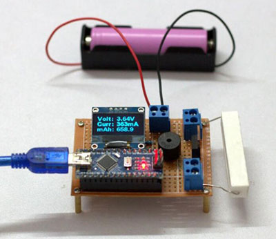
Fake NiMH and Lithium batteries have flooded the market. They advertise higher capacities than their true value. So, that’s where the Arduino battery capacity tester comes in to tell the difference.
Also, the device is effective for checking the capacity of recovered 18650 laptop LED batteries.
But how does the device work? Why do you need it? This article will answer all these questions, highlight detailed steps of building the device, and more.
Let’s begin.
Contents
Why Do You Need a Battery Capacity Tester?
Battery ratings are usually higher than their capacity, and the cells tend to age. So, If you plan to carry out the essential part of battery maintenance, it’s vital to get a battery capacity tester. And doing this test helps you know the remaining energy stored in your battery.
Additionally, it helps you know how much current your battery can deliver at a particular end voltage for a specific time.
Other benefits include:
- It helps you to know when to replace your battery.
- You’ll get insight into faulty intercell and weak cell connectors.
- It helps you know the position of your battery on its predictable life curve.
How Does a Battery Capacity Tester Work?
A battery capacity tester works by taking electrical capacity from a battery over a specific period. So, the amount of energy that the device extracts from the battery is equal to the battery’s ampere-hour rating.
Different batteries have different discharge limits. For instance, lead-acid batteries are 1.67V per cell. But, lead-acid batteries have a limit of 1.0V per cell. Hence, if you are using these batteries, you should have a minimum discharge of 20V and a nominal voltage of 24V.
The device may not give you the exact capacity of your battery. Instead, it will generate output equal to its ampere-hour rating. So, your battery is useful if it has a capacity of over 80% for an hour of discharge.
An ideal battery capacity tester ensures that it sustains a regular current of your battery’s ampere rating over a full discharge period. And the regular current will remain even if the battery terminal changes.
Also, the dynamic capacity tester helps to keep the discharge current constant by changing a battery’s load resistance based on the voltage. So, when discharge commences, the load resistance will change dynamically to sustain the required current. Also, the device will offer a resistance value at the terminal voltage.
DIY Arduino Battery Capacity Tester
Here, we’ll focus on creating a DIY Arduino-powered battery capacity tester in this section. You can run this project from home if you diligently follow the steps below.
The Necessary Tools and Components Needed for the Project
Tools
- Wire stripper
- Soldering iron
- Wirecutter
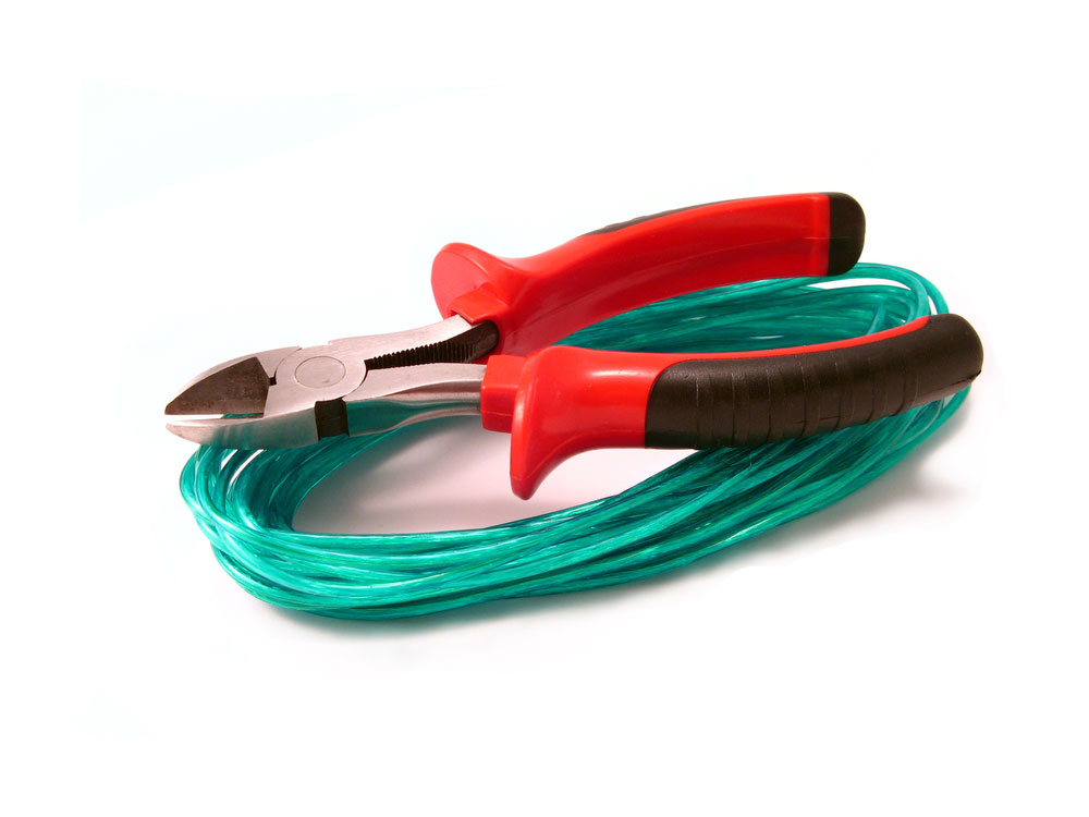
Wirecutter
- Clamp meter
Clamp meter
- Hot air blower
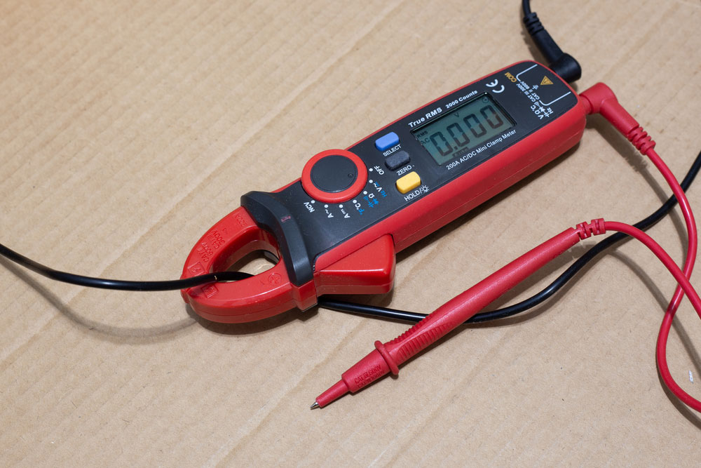
- Multimeter

Multimeter
Components
- Heatsink
- Push Button
- Ceramic ohm resistor
- PCB

PCB
- Opamp LM358
- Capacitor 220uF
- Screw Terminal
- Push-Buttons Cap
- PCB Stand-off
- Arduino Nano
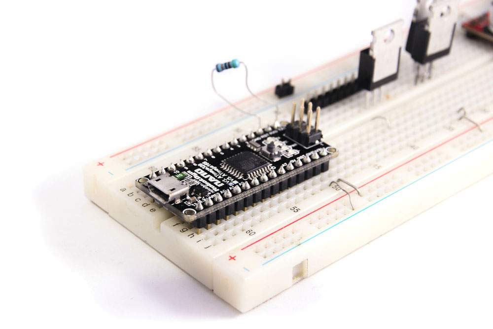
Arduino Nano
- Capacitor 100nF
- OLED display (0.96 inches)
- Prototype Board
- Power resistors (1M and 4.7K)
- Heatshrink Tubing
- LM385BZ_1.2 RF voltage reference
Steps
1. Draw the Battery Capacity Tester Schematics and Divide It Into Five Sections
- Buzzer circuit: You can use this buzzer circuit to notify the beginning and end of this project. Plus, an Arduino digital pin merges with the 5-volt buzzer.
- Battery voltage circuit: The Arduino analog pin measures the battery voltage. With C3 and C4 capacitors, you can easily filter noises from the steady current load circuit, and it can reduce the performance of the ADC conversion.
- Power supply circuit: It consists of a 9 volts DC jack, and it comes with two capacitors; C1 and C2. The Arduino pin (Vin) connects with the power output (Vout), and the Arduino voltage regulator steps down the current to 5 volts.
- Steady current load circuit: The Op-amp LM358 with two operational amps is the key element of this circuit. The R2 and C6 represent power resistors with a low-pass filter mechanism that removes the PWM signal Arduino pin D10 creates.
- UI circuit: Primarily, this circuit has a 0.96 inches display and two pushbuttons (down and up to push buttons for lowering and raising the pulse width of PWM). C7 and C8 are the perfect fit for debouncing push buttons, while R4 and R3 represent pull-up resistors suited for the down and up to push buttons.
2. How It Works
The OpAmp inputs Pin 2 and Pin 3 are one unified amp for this project. To open the MOSFET gate, you’ll have to establish the non-inverting input’s voltage by fine-tuning the PWM signal.
So, the current enters the R1 as the MOSFET switches on while creating a drop of voltage that gives the OpAmp negative feedback. This system allows the non-inverting and input voltages to be similar to the MOSFET control. Also, the load resistor’s current is directly proportional to the OpAmp’s non-inverting input voltage.
3. Calculating the Battery Capacity
The formula required to calculate the battery capacity is as follows:
- mAh = I x T
In the above equation;
- mAh = battery capacity
- I = current (mA)
- T = time (hours)
The discharge current is stable throughout your test because of the steady current load circuit.
4. Creating the Circuit for Arduino Battery Tester
First off, connect the circuit to a breadboard to see if it works. If it does, run the component soldering on the prototype circuit board.
Here are steps you can follow to achieve excellent results:
- Install the Nano by dividing the female header pin with diagonal nippers, giving 15 pins for each part. Then, ensure that both parts properly fit into the Arduino nano.
- Slice the 4-pin female header and use it to solder the OLED display to the board
- Afterward, join the remaining components and terminals to the board via soldering. Also, ensure to use colored wires to help distinguish them on the schematics.
5. Display the OLED screen
Use the 128 by 64 resolution OLED monitor with 0.96 inches to showcase the capacity, battery voltage, and discharge voltage. SDA and SCL are the two pins required for communication in the Arduino Uno.
To display parameters, use the Adafruit_SSD1306 library, which you can get on GitHub. After installing it, run the following connections in this order:
- 5V to VCC
- A4 to SDA
- GND to GND
- A5 to SCL
- Arduino to OLED
6. Install the Standoffs and Connect Buzzer for Warning Alerts
The piezo buzzer is the required component for warning notification throughout the test. It comes with two terminals; a longer positive leg and a shorter negative leg. Also, the buzzer has a sticker showing the positive and negative terminals.
If there’s no space to insert the buzzer on the prototype board, you can merge it to the main circuit board with two wires.
Here are the required connections:
- GND to Negative terminal
- Arduino to buzzer
- Positive terminal to D9
Afterward, install the standoffs by soldering them to the board. That way, you’ll have more space for wires and soldering joints.
7. Design Your PCB
Next, use the EasyEDA online app to design a schematic for your PCB.
With the schematic drawing, you can start arranging your PCB components together in an orderly way while occupying the slightest space. If you plan to place the PCB in an enclosure, verify that it comes with mounting holes.
Then, do the routing on the PCB with a tracking tool. The process involves connecting every component to avoid overlapping.
If you want to add text, use a silk layer on the board. Also, you can print a logo image on the board if you choose.
8. PCB Assembling
To assemble the components and parts to the PCB, you’ll need a multimeter, soldering iron, and nipper. The rule of thumb is to run the board soldering based on the height of the individual component or part.
Here are the assembling steps to take:
- Insert the legs of the components inside the PCB holes and turnover the PCB.
- Next, bring the soldering iron tip to the component legs at the back and solder the joints.
- Then, apply lead to the pad junction and cover it to allow the lead to flow around the component legs.
9. Arduino Codes, Software, and Library
In this stage, you’ll have to download libraries and Arduino code.
So, here are two libraries you need to download and install:
10. Do the Final Test
To run a final test, charge a battery with any good charger. Afterward, merge the same battery to a battery terminal before placing the current according to your requirement and holding the UP button for at least 10 secs. At this point, you would hear a notification sound to certify the beginning of your test procedure.
While testing the DIY Arduino battery capacity tester, check all the parameters on the OLED display. During the test, you’ll notice the battery discharging until it reaches a 3.2volts threshold, making delayed beep sounds.

FAQs
How do you test the capacity of a battery?
Connect the battery capacitor tester to your battery’s negative and positive contact; it will work by adding load. Then, it will observe the battery’s current and voltage. Typically, battery testers offer precise readings based on the type of battery it reads.
How do you monitor the battery on Arduino?
Connect your battery to the Arduino Vin, and you’ll see your battery’s voltage on display.
How is lithium battery capacity measured?
You can measure this capacity in Ah (ampere-hours). So, if you have 1 ampere-hour, you can draw 1 ampere from the cell in an hour.
Closing Words
The Arduino battery capacity tester is an excellent tool for keeping your batteries in good shape. So, you can choose to build or buy one.
While you’re at it, ensure that the device is compatible with your batteries. And the features are beneficial to your needs.
So, what do you think about the device? Please feel free to reach us with your questions or suggestions.