


What is an AM Receiver?
To begin with, AM stands for amplitude modulation. It is a strategy of electronic communication used in the transmission of data. Often, the most used transmission medium is via a radio carrier wave. However, in this modulation strategy, the radio carrier wave changes in amplitude with each message signal it transmits.
Therefore, the AM or radio receiver is an electronic device for receiving radio waves and making them usable. These could be moving images, digital data, or sound. However, more common is in reproducing sound transmitted via radio broadcasting stations.
AM receivers are of two stages: intermediate frequency and radio frequency. For example, using a common-base Armstrong oscillator of the variable frequency helps you send RF to an IF receiver. However, this variable frequency is different from the RF carrier frequency.
Tuning to the receiver channel simultaneously adjusts the RF and adjacent oscillator signals. Therefore, you have stations providing fixed carrier frequency to enable sufficient selectivity.
Types of AM Receivers
In most cases, the primary AM receivers in existence are of superheterodyne design.
A typical superheterodyne AM receiver comprises six components, namely :
- a radio frequency amplifier,
- a wire antenna,
- an IF section,
- a mixer/local heterodyne oscillator,
- a detector/amplifier.
Furthermore, the above subsystems are crucial for building a radio receiver. For instance, we have a simpler tuned radio frequency circuit or a TRF electronic amplifier circuit.
So, going on, we elaborate more on the types of AM receivers, which include:
- TRF Amplifier.
- AM Detection.
- Superheterodyne AM radio receiver.

(An example of an audio power amplifier circuit built using TPA3001D1)
TRF Amplifier
Usually, a radio frequency amplifier has a design that receives a narrow band of frequencies. One example of this narrow-band frequency is an AM band with a single radio station.
So, to achieve short wave bands from the tuned circuit, you adjust the resonant frequency. In addition, the input filter helps you exclude any unwanted input signal.
By default, though, the frequency range of AM shortwave bands is between 500kHz to 1500kHz. Therefore, with the baseband signal at about 5kHz, each station needs at least 10kHz within this spectrum.
In conclusion, there is a variation in bandwidth with the tuning of the circuit.

(A block diagram illustrating the operation of a tuned radio frequency receiver).
Superheterodyne Receiver
This radio receiver is responsible for boosting the RF audio signal sent to the mixer. Generally, it amplifies several stations simultaneously, though with an amplified input noise ratio. Still, it enables tuning in broadcast bands.
On the other hand, the mixer has another input in high-frequency sine sound waves. This result is largely due to the action of the local heterodyne oscillator. However, these sine sound waves are often above 455kHz (the standard station carrier frequency for AM receivers). So, the mixer combines inbound carrier waves with the oscillator to resolve this. As a result, it then creates a sum and difference frequency.

(A block diagram of a superheterodyne receiver operation).
However, an ideal mixer combines two weak signals and brings about a couple of new frequencies. These include:
- The original dual frequencies.
- A DC level.
- Harmonics of the dual input frequencies.
- The sum and difference of these two frequencies.
- As well as the sum and difference of the fundamental harmonics.
The two primary station frequencies are the Local Oscillator Frequency and Image Frequency, respectively.
AM Detection
We have the coherent radio receiver among the basic AM detection techniques and the non-coherent one. However, the more straightforward approach is the non-coherent type of radio receiver.
By contrast, the non-coherent method does not depend on carrier signal regeneration. With the aid of a diode and electronic audio filters, you detect and remove the modulation envelope.
On the other hand, the coherent detector stage depends on regenerating and mixing the carrier and AM signals.
In general, AM detection is into three such as:
- Envelope detector.
- Square detector.
- Synchronous detector.

(A circuit diagram of the envelope detector. It shows the connections of a bypass capacitor in parallel to the coil and a diode in series).
How to Construct a Simple AM receiver circuit
To construct a simple AM radio receiver circuit, you first need to assemble a few hardware components, thus:

(A top view of a simple AM radio receiver circuit using five transistors).
Materials needed for the circuit

For the single-transistor build, here is the complete parts list. All of these components are inexpensive and easy to source, and you can salvage the coil and the variable capacitor from an old AM compact radio.
| Serial Number | Components | Value | Quantity |
| 1 | Headphones | N/A | 1 |
| 2 | Resistor | 22Ω, 820K | 1, 1 |
| 3 | Transistor | BC547 | 1 |
| 4 | Coil | 80 turns | 1 |
| 5 | Diode | OA91 | 1 |
| 6 | Long antenna wire | N/A | 1 |
| 7 | Capacitor | 100nF, 10nF | 2, 1 |
| 8 | Variable capacitor | 365pF | 1 |
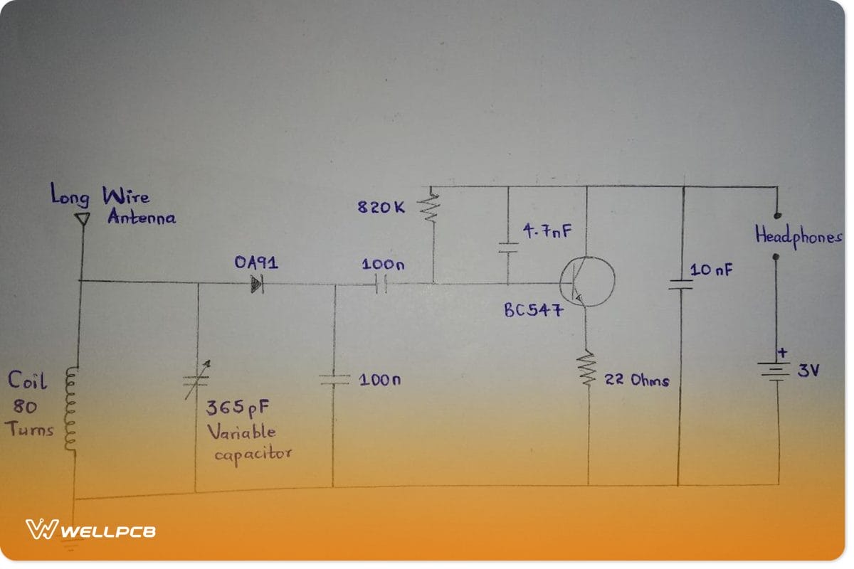
(The single-transistor AM receiver circuit schematic).
Circuit Design
Furthermore, we illustrate the design of a simple AM receiver circuit with the aid of a video attached below.
Circuit Operation

(A schematic showing a simple AM radio model).
So, before constructing a simple AM receiver circuit, it is essential to have a good understanding of its working principles. For that reason, we have included a block diagram above for visual representation.
For the primary circuit, you need a single transistor, a 365pF variable capacitor, and the coil L, amongst others. These essential passive components, in conjunction, help to send signals via the wire antenna. Therefore, they work as a signal-receiving cable.
Going further, the OA91 diode D1 identifies the original radio signal. However, the signal is relatively insignificant. As a result, the BC547 transistor amplifies the weak signal.
On the other hand, you need a coil L of 80 turns of 26 s.w.g.., so you may twist the enameled copper coil of wire on a cardboard tissue paper roll to achieve this. Otherwise, open up an AM compact radio and use the coil wound inside.
In summary, a fully functional radio receiver requires an RF component area, an IF section, and a mixer (RF-to-IF converter). Also, it requires a demodulator and, of course, an audio speaker.
The demodulator, though, only functions with an incoming radio signal when converted. This conversion of incoming radio signal is from carrier frequency to intermediate frequency. In the end, the radio receiver optimizes and utilizes the converted audio frequency.
Upgrading to a 2-Transistor AM Receiver Circuit
Once your single-transistor receiver works, a natural next step is a two-transistor version. It splits the work between two stages – one transistor demodulates the signal while the other amplifies the audio – so the output is loud enough to drive a small speaker instead of headphones.
Here are the materials you need to prepare:
| S. No | Components | Value | Qty |
| 1 | Capacitor C1 | 500pF | 1 |
| 2 | C2 | 0.1uF | 1 |
| 3 | C3, capacitor C4 (non-polarized capacitor) | 470pF, 47uF | 1 |
| 4 | T1 | 2SC3112 | 1 |
| 5 | T2 | 2SC3122 | 1 |
| 6 | Speaker – from a small earphone | 10k | 1 |
| 7 | L1 – an ordinary antenna coil | 1 | |
| 8 | R1 | 1K | 1 |
| 9 | R2 | 1M | 1 |
| 10 | R3 | 39K | 1 |
| 11 | R4 | 6.8K | 1 |
| 12 | R5 | 2.2K | 1 |
| 13 | TRIM | – | 1 |
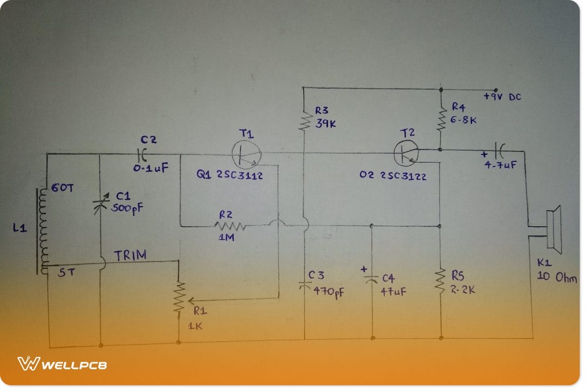
(The 2-transistor AM receiver circuit diagram).
In terms of the basic circuit functioning:
- First, the tank circuit consists of capacitor C1 and coil L1.
- Secondly, the transistor Q1/T1 is a demodulator – the demodulated signal is at Q1’s base.
- In addition, further amplification is achievable when the base of Q2 is in combination with the audio signal. Then, the system avails an amplified audio signal at Q2’s collector.
And here is how the circuit operates in practice:
- First and foremost, the antenna coil will collect MW signals from the surrounding air.
- Then, before proceeding to the next stage, the trimmer will first set and then tune the frequency.
- In the third stage, T1 acts as both the demodulator and high-frequency amplifier. T1 extracts audio from the signal it receives and then takes it through an amplification process before passing it to the last stage.
- Finally, T2, which is an audio amplifier, further amplifies the demodulated signal at its base. Often, the signal amplification here is audible enough on the connected speaker, loud and clear. But, to avoid a bad speaker, ensure it is 10 ohms.
AM Receiver Applications
Typically, a simple AM receiver detects amplitude fluctuations in radio waves. An example is in a crystal radio circuit like the customized crystal earpiece. Here, it operates at a frequency response, resulting in amplification changes in signal voltage. Other applications include:
- In electronic analog telecommunication systems.
- Another common use is in the wireless transmissions of data via radio waves.
- In addition, it is crucial in AM radio broadcast bands and radio communication.
- Also, for use in analog mixers used in audio control.
- It is vital for use in two-way radios.
- Furthermore, it is a significant part of devices like computer modems, remote controls, etc.
- For use in dispatch radio systems of the navy and police.
- Also, there are some outdated applications of AM receivers. Some include telephones, transmitting Morse codes, controlling television screen pixels, etc.
Conclusion
The AM receiver is an electronic system for modulating amplitude signals. AM receivers are a mainstay in modern technology because they are essential in radio listening and other radio transmission applications. Other diverse uses range from radio communication and data transmission to audio amplification.
Now, we have learned how to build a simple AM receiver. However, if you need further directions on handling more complex projects, contact our team for assistance.


