Contents
Making PCBs Tick: A Look at Circuit Board Components
Basic printed circuit boards (or bare boards) are composed of copper traces encased in fiberglass substrates. Manufacturers must add electronic components before becoming fully functional PCB assemblies (PCBAs).
Electronic components extend the functionality of the PCB. If electrons are like cars and the bare circuit board is the road, components act as traffic signs, lights, and lane markings.
While road traffic signs and controls are usually passive (they don’t take full control of your vehicle), electronic components can also be active.
This leads to two main classifications of electronic components: passive and active. But there’s also a third classification: electromechanical. Let’s take a closer look at these classifications.
Passive Components: The Road Signs of the Circuit Board
Passive components don’t need a dedicated power source. Instead, they receive the energy that flows through the circuit and either soften it, increase its voltage or current, divert it, or store it in a field.
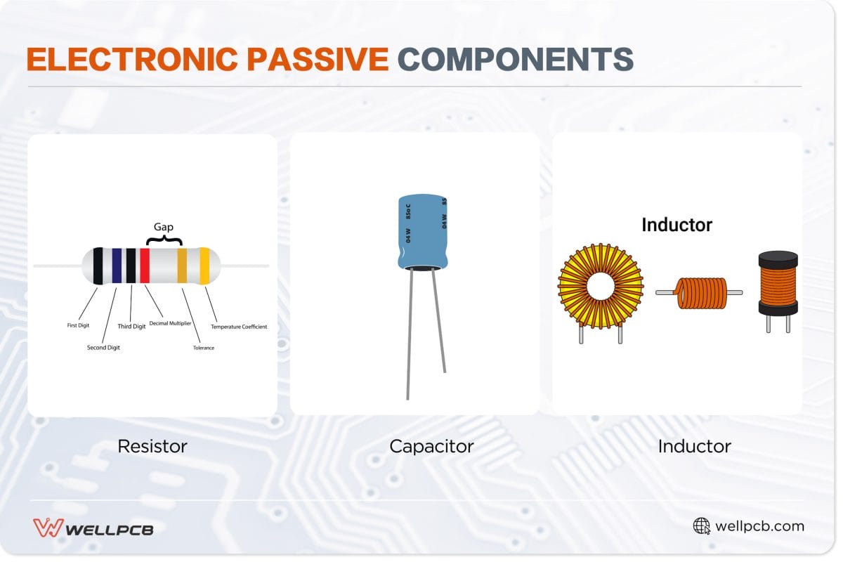
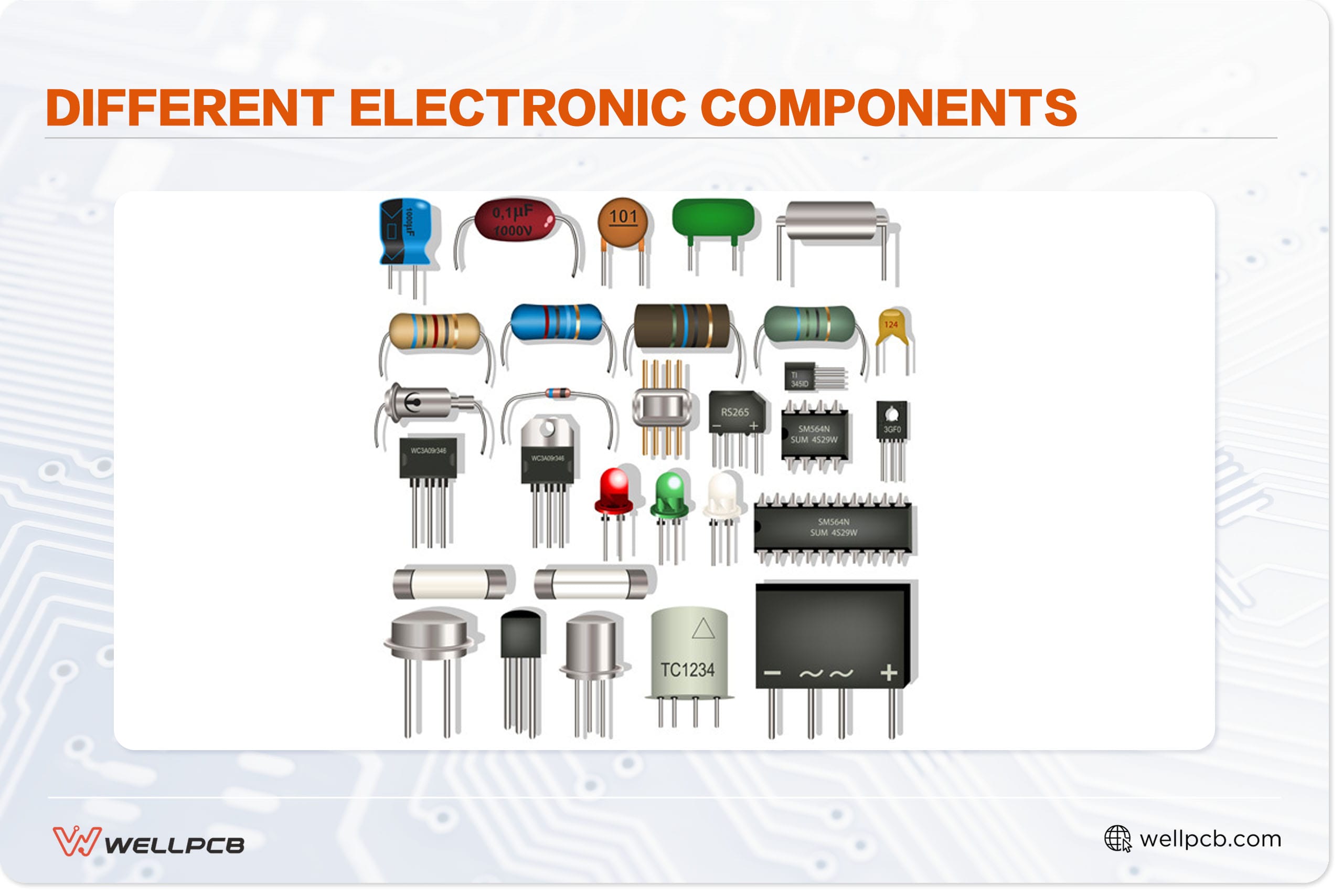
Passive components are typically two-terminal devices. Three of the most common types are:
- Resistors: These mainly reduce or control the intensity of the current. Using our road traffic analogy, resistors are comparable to the speed limit, yield signs, merge signs (as voltage dividers), or stop signs (infinite resistance). They can also act as speed bumps.
- Capacitors (AKA condensers) are electronic components like garages or parking lots, mainly storing energy from a circuit. Unlike batteries, which use chemical energy to store charge, capacitors use an electrical field. Most capacitors consist of two electrical conductors separated by a dielectric substance.
Non-polarized capacitors are typically classified by their dielectric material, including glass, silicon, film, and ceramic. Polarized capacitors, such as polymer and electrolytic capacitors, are named after the material that comprises their electrolytes.
- Inductors: Similar to capacitors, inductors store charge in a magnetic field rather than an electrical one. While capacitors respond to a drop in voltage, inductors respond to a drop in current.
Engineers can also use inductors to separate signals of different frequencies, block alternating current (AC) to allow direct current (DC) or serve as chokes.
Active Components: The Brains Behind the Operation
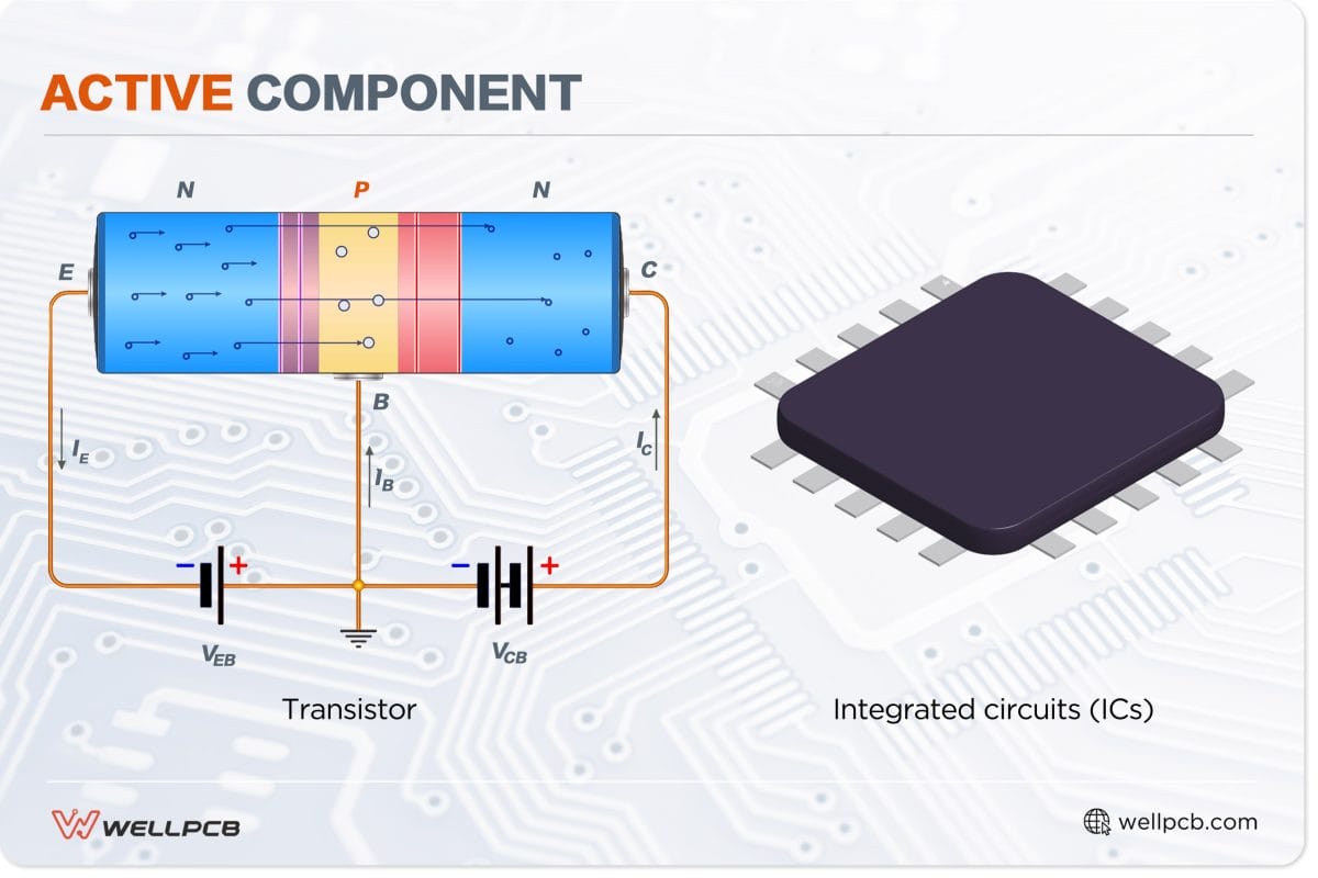
The active components are complex circuit board devices requiring a dedicated energy source. As a result, they can add power to the circuit. The two most common types of active components are:
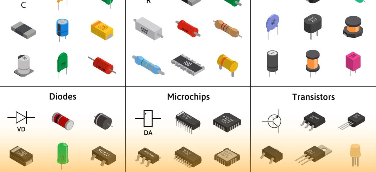
- Transistors: Mainly used for amplification and switching, transistors consist of three layers: the emitter, base, and collector. Transistors come in various types and configurations. In an NPN configuration, a heavily doped emitter passes charge carriers through a lightly doped base into a collector, recirculating amplified current into the circuit.
Note that this is a simplified explanation. Transistors are complex devices whose functions require a deep understanding of physics.
- Integrated circuits (ICs): Often referred to as chips or microchips, these are condensed circuits consisting of miniaturized transistors, capacitors, and resistors etched into silicon packages.
Examples of ICs include microprocessors (CPUs), random access memory (RAM), and controller chips. Without ICs, modern PCs would not exist.
Electromechanical Components: The Bridge Between Circuits and the World
As the name implies, electromechanical components contain both electronic and mechanical properties.
While the function of passive and active components can seem mysterious, as we rarely see their inner workings, the purpose and function of electromechanical components are far clearer.
For instance, you can see the light generated by an LED, the motion from a fan or motor, or the buttons on a push switch.
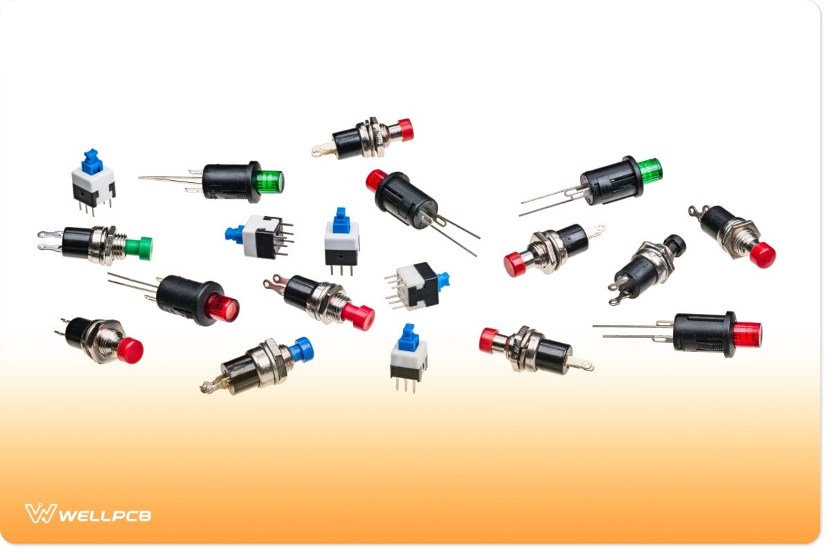
Various Miniature Push Button Switches
That said, not all electromechanical components have perceivable functions. Resonators, crystal oscillators, and other piezoelectric components are electromechanical with less obvious mechanisms.
Their mechanical parts are hidden behind encasements or work so subtly that the human eye or ear can’t easily detect their movements.
Connectors are another common and useful electromechanical component. They allow us to connect circuit boards to other boards and larger electronic components, making PCBAs the building blocks of large, complex electronics and systems.
The Big Picture: How Components Work Together on a PCB
As mentioned, each PCB and PCBA serves a specific purpose. Whether a motherboard or a simple circuit, the PCB’s structure, and its components’ configuration will determine its purpose and how well it functions for that purpose.
Like the human body and its organs, each electronic circuit component has a specific function and works with other components to produce a unified result. Just as you can have two kidneys in the body, you can have two resistors in a circuit.
For example, a simple circuit designed to power an LED may consist of a power source (such as a battery), a resistor, and a diode. The resistor and diode are passive components that control the intensity of the current from the power source.
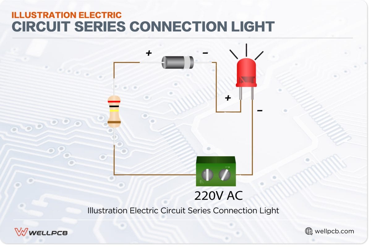
You can add relays, capacitors, and switches to convert the above into a blinking LED circuit. Alternatively, you can add a parallel circuit with a green LED. This entire circuit can then be integrated into a separate system to display the functional state (on or off).
Getting such systems to work is only part of the challenge. You also need to ensure they can be built and function as needed. Consequently, the layout and configuration of your circuit board require careful consideration. This highlights the importance of effective PCB design.
Beyond the Basics: Exploring Other PCB Components
By planning and employing good PCB design, you can determine whether more advanced components are needed, such as:
- Diodes primarily ensure unidirectional current flow, preventing current from flowing in the opposite direction and damaging other components.
- Fuses: These passive components prevent overcurrent. When too much current flows through the fuse, an element melts and breaks the circuit.
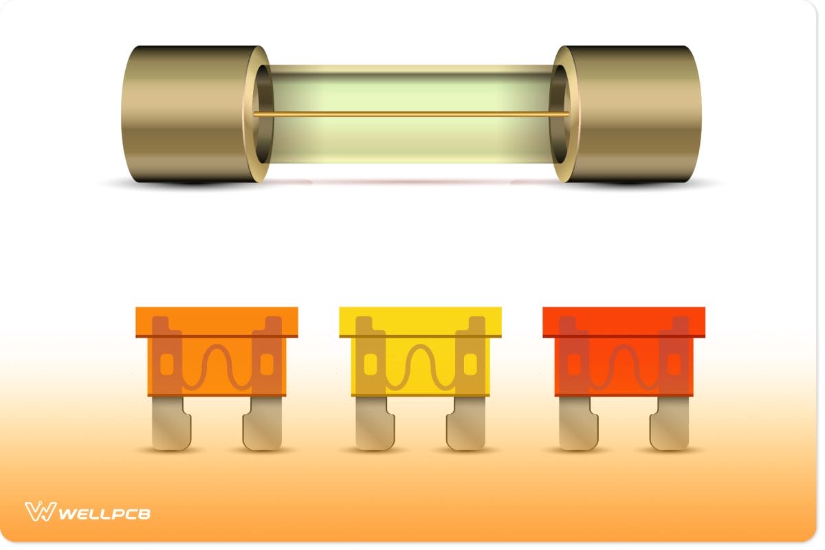
Fuse Electrical Protection Component
- Sensors: These electromechanical devices produce a signal from physical environmental phenomena. Examples include pressure sensors, accelerometers, and motion sensors, some of which are embedded in most smartphones.
Partner with PCB assembly experts
Whether based on wires or printed boards, circuits would be useless without electronic components.
Printed circuit boards serve as a foundation and network for electronic components to communicate with each other.
All these components work together to produce an output that becomes part of a fully functional electronic device.
This is why PCBs are the heart of all modern electronics.
Learn more about our high-quality PCB assembly services or get a free quote for your next project. Or, to delve deeper into the world of electronics and PCB components, explore our resources page.