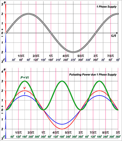
Define Impedance, donated Z, in electrical devices, refers to the amount of opposition faced by direct or alternating current if it passes through a conductor component, system, or circuit. When the current and voltage are constant, the Define impedance is null, and thus the value is never null in the event of alternating current.
Define Impedance is the sum of reactance and resistance of an electrical circuit and measured in Ohms. Impedance is a course characteristic that must be taken care of while designing a printed circuit board. PCBs with impedance requirements nullify the changes in voltage, leading to a gadget or appliance that operates as expected.
Contents
Why is it Essential to Understand Define Impedance on PCBs?
It’s all about matters to do with efficiency. Theory indicates that maximum signal transfer takes place when the entire impedances found on the signal path match. Control impedance is necessary for printed circuit boards that operate under high frequencies while processing high-speed digital signals. Define Impedance control is essential for PCB manufacturers and is fast becoming critical in digital applications of high speed, RF applications, and telecommunications. Without understanding matters to do with impedance on printed circuit boards.
We would not be in a position to know how changes in impedance, a mismatch in impedance, or even improper impedance brought about wrong geometry distorts signals. In short, impedance can be equated to rock ‘n’ roll, and getting to understand it is a bit complicated. But again, you don’t need to comprehend everything about Define Impedance to “get” it.
In summary, a printed circuit board with full impedance requirements will invalidate all changes in voltage. It will lead to gadgets or devices work as expected. At WellPCB, we can easily recommend software programs designed to detect reactance flow and resistance efficiently, providing you with all the specs you need. We will use this data to create a custom PCB for you.
How Can Define Impedance on PCBs Get Controlled?
For example, in our satellite/TV cable, the antenna acts as the source, the TV set the load, and the coaxial cable acting as the conductor. The cable consists of insulators, conductors, and their dimensions, along with their electrical characteristics measured to control the cable’s electrical impedance.
For signals on the PCB to effectively transfer along the path from the message’s source to a load, impedance control is necessary. Without controlling impedance, chances of such signals moving useful will be challenging if not hard. With controlled Define Impedance, expect your board to work as expected without any failure or disappointment.
But achieving such is not hard as it may sound. For the signal to effectively move from the source to the load, impedances have to match. Therefore, the input impedance of the output impedance of the reference track and load impedance must match. This way, the signal will move from the source to the desired location without difficulties.
To ensure you achieve impedance control, your manufacturer will probably work with the stated parameters coming from the field solver first. After that, tests on PCB impedance may have to be carried out, and if necessary, some changes could be undertaken to produce or come up with a PCB that will function as desired.
Examples of Define Impedance Control
Some of the most common or apt examples of controlled Define Impedance are the cables connecting the antenna to people’s television sets. The wire may be a coaxial cable consisting of a round and inner conductor separating it from an outer cylindrical shield.
The dimensions, insulator, conductors, and electrical characteristics are carefully controlled to determine the shape and interaction of their electrical fields. This will go a long way in deciding the cable’s electrical impedance.
An apt example is in place. To get the best signal, the antenna or satellite antenna impedance must match the cable’s impedance. On the other hand, the cable has to match that of the TV also. Now transfer this thinking to PCBs and imagine if the desired signals don’t reach the intended destination due to a mismatch in impedance.
Based on the above, nothing will work as desired if a mismatch happens or is suspected. Therefore, controlling impedance on PCBs then seems like a good idea to undertake. But again, how does one achieve this without too much difficulty?

How Does Define Impedance Control work on PCBs?
Before deciding the kind or type of impedance control service that will suit your needs for your boards, you’ll need to comprehend impedance control basics. What is impedance control, and how exactly does it work? First, there are three basic levels of service concerned with impedance control. They include:
• No Impedance Control – No additional design elements are required to achieve the correct impedance because the impedance tolerance is very loose. This situation will result in a less expensive and faster-completed PCB.
• Impedance Watching –Here, a designer outlines impedance control trace with the provider, only adjusting the dielectric height and trace width accordingly. Once the user specifications get approved by the manufacturer, PCB manufacturing can begin.
• Impedance Control – The manufacturer makes the PCB board doing its best to hit the required impedance.
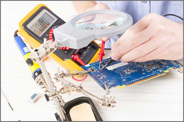
How to Measure on PCBs
Among other challenging activities or exercises that exist out there, arguably measuring impedance on printed circuit boards is one of the most challenging tasks. Those who have tried it before have argued that measuring Define Impedance values within a PCB is not always easy as it seems. There are plenty of complicated steps and equipment that are necessary here.
Other factors such as connections, accessibility, length of traces, and branches off tracks can make getting an accurate reading challenging. A Time Domain Reflectometer, also known as TDR, is a standard method of measuring impedance. This reflectometer sends some signal along a line and then measures the part of the message reflected if an impedance mismatch happens.
For measurement, it’s advisable to use high-quality probes and cables, and if RF adapters are necessary, you need to resort to calibration quality adapters. Also, it is essential to use gated cursors to obtain the mean value in this range. Of importance to understand is that reducing the bandwidth degrades resolution though it provides or brings about a lower noise.
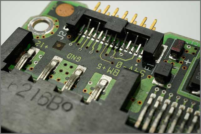
Factors That Can Affect Define Impedance on PCBs
The most crucial factor affecting the impedance consistency of a printed circuit board is the uniformity of thickness at different locations and line width. If the line is less than 25mm from the board’s edge, the line impedance value will be 1-4 ohms smaller than the one in the middle. The position’s impedance value is not severely affected if the line is more than 50mm from the board’s edge.
In short, some of the factors that affect impedance PCB tolerance are aspects such as materials’ tolerance and resin content. That’s not all. Others include the trace width and height located at the top and bottom of the board. If you give WellPCB your set of patterns, we will combine them into a single circuit board. Manufacture your PCB with the right positions and pattern sizes with specific tolerances. It is vital to ensure that your manufacturer can provide you with the correct location, size, and endurance. If such doesn’t happen, the chances are that your board may end up being useless.
Among all the most factors that affect PCBs’ impedance, Dielectric thickness holds the most significant percentage (45%). Followed by trace width (25%).Dielectric constant (15%).Copper thickness (10%). And finally, solder resists (5%).
Conclusion
Define Impedance is the sum of reactance and resistance of an electrical circuit expressed in Ohms to sum it all up. On PCB boards, matters to do with impedance need to be taken seriously since such will affect the signal transmission on the PCB. An impedance analysis is necessary when fast switching signals at low currents have to be transmitted since they are mainly susceptible to interference. But to avoid or minimize reflections occurring along the printed tracks, matters to do with impedance control have to be factored in to prevent some distortions. WellPCB is one of those manufacturers serving hundreds of customers on the planet thanks to their technical support before ordering, rich experience in impedance controlled boards manufacture, and 100% impedance matching experience.