Contents
1. What is an Electronic Schematic?
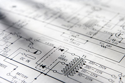
First of all, a schematic is an abstract diagram to show how a system works. It often uses easily recognizable symbols to deliver what each part of the system represents.
In the same way, we use schematics when describing electrical diagrams. Therefore, this brings us to the term electro schematic.
Contrary to popular opinion, electro schematic is more than just electronic symbols. It is the graphic design basis for assembling electronic components and building a more extensive circuit.
Most times, it is a complete paper design with pre-printed adhesive symbols. Other times, it is best to design this blueprint on a computer. Some helpful software for that purpose includes Altium Designer, Cadence Or CAD, Mentor PADS, Upverter, and Zuken CADSTAR.
2. Schematic Diagram vs. Circuit Diagram
, a schematic diagram is more straightforward than a circuit diagram. The main idea is to group the parts of the system into inputs and outputs. It, however, shows the fundamental components needed for the integrated circuit. These include resistors, capacitors, transistors, etc.
Using a schematic diagram, as a result, allows for easy simulation and layout of the IC. Hence, applying current and voltage laws such as Ohm’s and Kirchoff’s is easy. A circuit analysis package such as SPICE is helpful at this stage.
On the other hand, a circuit diagram is more detailed. It reveals every active and passive component needed for the IC. For instance, complex features like logic gates, external ICs, and connectors are all present in a circuit diagram.
In the end, the two types of diagrams are the initial CAD models before they advance to the PCB layout phase.
3. Circuit Schematic vs. Block Diagram
Most times, people mix up circuit schematics with block diagrams. They, however, are not the same.
A block diagram is a basic sketch that begins the overall PCB design. In other words, a circuit block diagram shows how the system works from a realistic point of view. In some ways, it is a semi-schematic diagram. Its focus is not on the circuit components. Instead, the block diagram shows how the system handles digital and analog data signals. Notwithstanding, a block diagram may involve electronic components if they help to explain the system’s functionality.
Meanwhile, the circuit schematic breaks the block diagram further into detailed parts.
4. How do You Get Electronic Schematics?
You only need to follow these few steps to get started.
Steps to follow
- First of all, select an electronic device of interest.
- Then, locate the FCC ID number labeled to the device. Most electronics, by default, bear FCC certification. This certification is in the form of a unique ID number from the US Federal Communications Commission. However, it is more common among RF-transmitting devices.
- After getting the FCC ID (find this on the device casing), log onto the website https://www.fcc.gov/oet/ea/fccid/.
- Once there, input the “applicant” or “grantee” code. By default, this code comes from the first three characters of the FCC ID. The remainder is the Product Code, which consists of dashes and hyphens.
- After entering the code, click on search.
- At this point, a pop-up list of submitted applications concerning that device shows up.
- Click on options to see further details. Thus, all information about the device should become available for download as PDFs. These include internal photos, exterior photos, test reports, and even the device’s original cover letter application.
- However, specific information and documents are not available on the FCC website a few times. This non-availability is a result of certain vendors withholding this information as confidential.
- At this stage, you have all the necessary schematics and data for a true DIY circuit adventure.
5. Some Electro Schematic Symbols
A few graphic symbols are found on almost any electronic circuit diagram.
R = Resistor.
C = Capacitor.
D = Diode.
L = Inductor.
Other electronic components include:
- T = Transformer.
- F = Fuse.
- P = Connector.
- U = Integrated Circuit.
- H = Hardware.
- Q = Transistor.
- Y = Crystal.
- BT = Battery.
- J = Connector
- K = Relay.
- S or SW = Switch.
6. Some Simple Electro Schematics
Below are a few projects worth trying out using electro schematics.
BA1404 HI-FI Stereo FM Transmitter
Although this FM transmitter requires lots of tweaking and testing to get the desired result, the aim is straightforward. The schematic tests are existing BA1404 FM transmitter designs to compare their performances and weaknesses. Eventually, the new method produces improved sound quality, stable frequency, and transmitting range.
For assistance, see the video below on building an FM transmitter.
BH1417 PLL Stereo Transmitter
The schematic for this device, in particular, packs many features in one tiny package. For example, there is a stereo encoder, low pass filter, limiter, PLL solid frequency transmitter, RF output buffer, and so on.
Phone FM Transmitter
This device is for connecting a telephone line to an FM band. It allows you to send a phone conversation via the FM band using the telephone handset. To that effect, you tune transmitted signals with the FM receiver.
One unique feature of this circuit is that it does not need a battery. Also, it uses an LED indicator when in “On Air” mode and a switch to control the transmitter.
Single Chip FM Transmitter
This FM transmitter chip is handy for linking your music player to a portable radio. For instance, it lets you play the same music on your sound system on your mobile radio while on the go. Interestingly, it operates on a voltage supply of 3-5V only.
Conclusion
In summary, electro schematics are the building blocks for any larger circuit or IC. Irrespective of the chart used, they all use unique graphic symbols for each component and their connections. The final PCB layout, in most cases, begins from a block diagram before advancing to a circuit schematic or diagram.
For reference, we have cited some examples of electronic circuit schematics above. However, contact our team if you still need professional assistance in similar personal projects.


