
Contents
Meaning of Inverter Circuit
Inverter circuit converts Direct Current electricity to Alternating Current to supply power to electricity grids or stand-out systems. In other words, it’s the device that changes DC (Direct Current) to AC (Alternating Current).
How Does an Inverter Circuit Work?
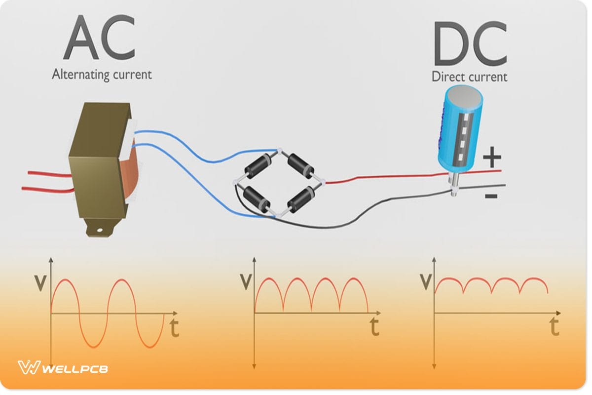
It is effortless; the converter circuit continuously converts Alternating Current to Direct Current under rectification. In other words, the magnitude and wave’s direction change regularly over time because the Alternating Current is a sine wave.
Thus, a diode helps pass electricity to convert it to a direct current, however not in a reverse direction.
If the Direct current passes via the diode, it’s just the forward direction that will pass the electricity, making the positive peak show. This means the cycle’s other half will be wasted since it doesn’t negatively go to its peak.
Therefore, the diode structure is made like a bridge to go through the negative peak via a forward way. To this end, its name is full-wave rectification since it transforms the negative and forward wave peaks.
Meanwhile, the rectification of full-wave alone can’t create smooth waveforms, while the traces of rippled voltage and alternating current fluctuations would remain.
Thus, to clean up, the capacitor would be discharged and charged repeatedly. Therefore, smoothing and exchanging the waveform near Direct Current.
Further, this simple inverter circuit will then output AC with varying frequency and voltage. The AC/DC conversion process will switch the power transistors like the Insulated Gate Bipolar Transistor (IGBT) while changing the OFF/ON intervals to produce pulse waves alongside diverse widths.
After that, it joins them to a quasi-sine wave known as PWM (Pulse Width Modulation).
The computer automatically controls the width of the pulse. For example, some assigned one-chip computers control the motor, which includes a PWM function pre-installed product.
Consequently, it is feasible to produce a different frequency of pseudo-sine waves while controlling the motor rotation speed by outlining the desired parameters.
In another vein, it’s vital to add that the current pulse number classifies Rectifier circuits and inverter pulse numbers, which flow to the Direct Current side of AC input voltage.
Furthermore, the associated rectifier circuits can be 12-pulse rectifiers, 18-pulse rectifiers, or even more. Meanwhile, rectifier circuits work in the inversion mode when controlled.
The above diagram’s configuration is now popular in Alternating Current power supplies with an adjustable speed drive application. In the meantime, if additional inverters join together, an 18-step inverter obtains with another three inverters.
A picture of an electronic diode component
Inverter Circuit Output Waveforms
An inverter might create a modified sine wave, square wave output, and pulse width modulated wave, pulsed sine wave, output voltage waveform, or even sine wave based on the circuit design. Popular kinds of inverters create quasi-square waves or square waves.
A measure of the sine wave’s purity is the entire harmonic distortion (THD). For example, a 50 percent duty pulse square wave is like a sine wave of 48 percent THD.
In the meantime, the commercial power distribution grid is just less than 3 percent THD at the wave shape of the consumer’s connection point. More so, the IEEE Standard 519 advises less than 5 percent THD for systems that connect to the power grid.
However, the two main designs abound to create a household plug-in voltage from the lower-voltage DC source. Number one utilizes the switching boost converter to produce a higher-voltage DC and later convert it to AC.
At the same time, the second design converts Direct Current to Alternating Current at the battery level while using a line-frequency transformer to create output voltages.
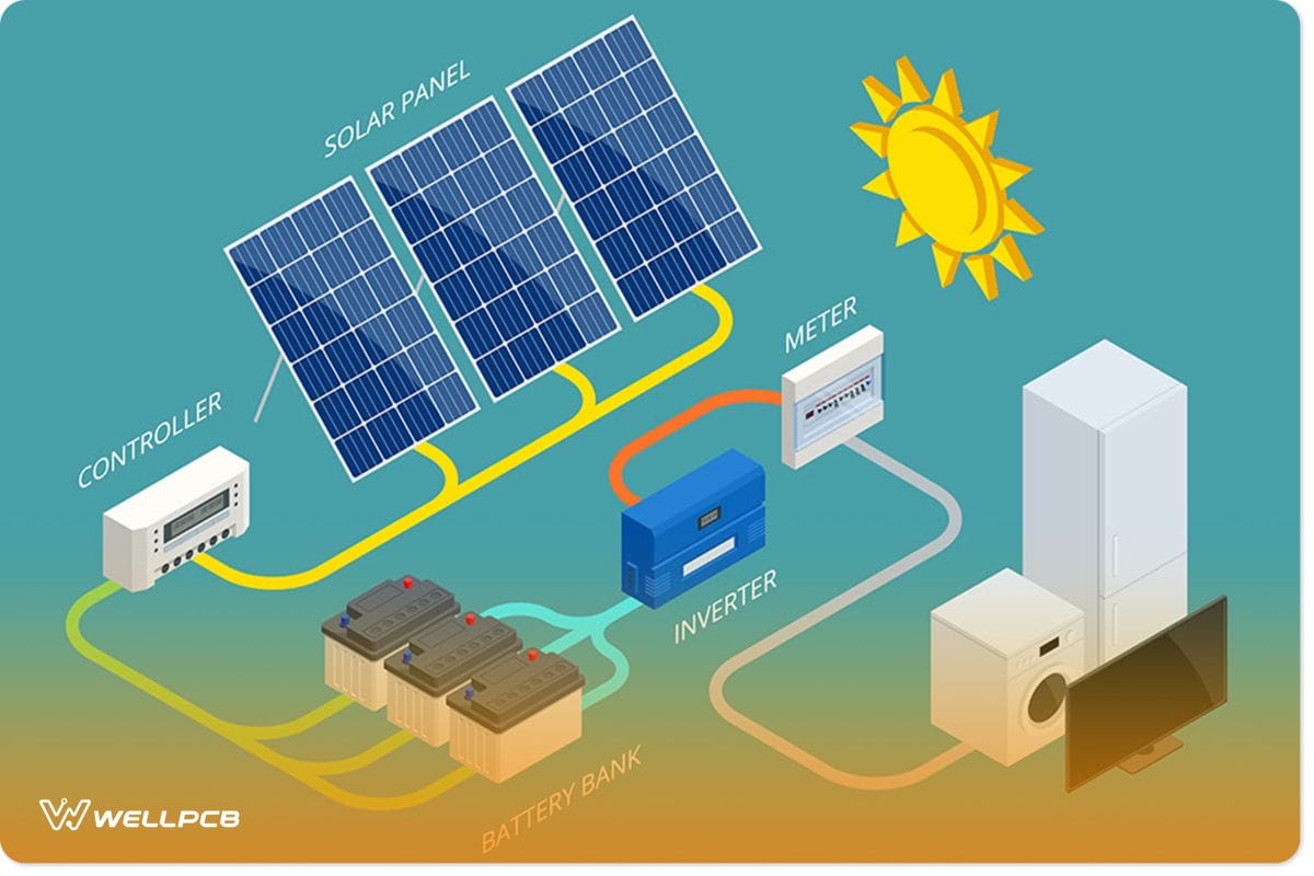
An image of vector/isometric solar panel cell system
How to Build a Power Inverter Circuit
Needed Components
The main components are;
- R1, R2= 100 Ohms./ 10 watts wire-wound.
- T1, T2 = 2N3055 power transistors.
- R3, R4= 15 Ohms/ 10 watts wire-wound.
- Transformer= 9- 0- 9 Volts / 5 Amps.
- Aluminum heat sink= cut as per the required size
- Automobile battery= 12 Volts/ 10AH.
- VentilateWith a simple inverter, you can control rotation speed. metal cabinet= as per the size of the whole assembly
- Primary coil/10-0-10V, 750 mA- secondary coil
Other fundamental components include;
- 12v Battery.
- 2N2222 Transistors.
- Resistor.
- 2N2222 Datasheet.
- IRF630 Datasheet.
- Acid battery, single battery, and extra battery
- Power transformer.
- Aluminum heat.
- 9-0-9V, 5 AMP
Steps to Build a Power Inverter Circuit
First Step
First, get an aluminum sheet and cut or divide the sheet into two parts of about 5×5 inches. While at it, drill holes that will fit power transistors. Meanwhile, note that the holes should be about 3mm in diameter.
In addition, make or drill appropriate holes to make it firm and straightforward in fitment on the inverter cabinet.
Second Step
Next, carry the resistor and link it at a cross-mode using the arms of the transistor, just like the circuit displayed below.
Third Step
Another thing is to fix the transistors strongly on the heat sinks using bolts or nuts.
Fourth Step
After that, connect resistors, heat sink, and transistors assemblage through the transformer’s secondary circuit.
Fifth Step
Finally, put the transformer assembly and complete PCB in the metal cabinet that has good ventilation. Attach the output/input points plus the fuse holder alongside the cabinet and link them.
Now, the inverter is ready. The inverter can help as a case for housing the Inverter Circuit. In addition, note that the output voltage, frequency, and input voltage, voltage level, and general power handling rest on the specific device design. As a result, you need to consider everything before circuit construction.
How to Test it
The operational check of your circuit before use on a full scale is necessary. To test the device, carry a 50-60 watt bulb connection using the o/p socket of the inverter. After, put a battery (12 volts) using the i/p socket of the inverter.
The bulb would light up clearly and brightly, indicating that your circuit connection is correct and the out inverter is prepared to carry on the field. Nevertheless, when the bulb doesn’t light up, you have to recheck your connections.
Inverters react quicker than normal generators to influence changes around the grid frequency. Thus, your inverter needs to synchronize with the grid frequency.
Note;
- To begin with, know that a transformer that increases a voltage from primary to secondary is a step-up transformer. The step-up transformer converts low-current power and high voltage into high-current power, low-voltage.
- More so, you should know that Switching loss is a major part of the entire inverter losses in higher switching frequencies. Thus, switching frequency optimization is essential to lessen the THD and switching losses around power devices.
- Consequently, with a 5-kW three-phase PWM inverter, the proposed gate control method validity plus the optimization medium evaluates using the digital gate drive ICs.
Classification of Inverter Circuit
The classification of inverters includes the types based on source, output, and type of load. They are;
Output Features
- Sine Wave Inverter
- Square Wave Inverter
- Modified Sine Wave Inverter
Source of Inverter
- Voltage Source Inverter
- Current Source Inverter
Type of Load
- Single Phase Inverter
- Half-Bridge Inverter
- Full-Bridge Inverter
- Three Phase Inverter;
This can work in two modes depending on the gate pulse degree. They are-
180-degree mode; the conduction time in this mode of operation for thyristor is 180 degrees. 120-degree mode; this mode of operation, on the other hand, conducts only two thyristors at a time.
- Output Level Number
- Regular Two-Level Inverter
- Multi-Level Inverter
Other classifications are:
Micro-Inverters- It is a small inverter for individual solar panels.
CMOS Inverter- (Complementary Metal-oxide Semiconductor) CMOS offers logic functions. It is a main integrated circuit component. CMOS inverter is the field-effect transistor comprising the metal gate on a semiconductor. To this end, the CMOS inverter is in several electronic devices while offering data around small circuits.
Common Inverter Circuit Applications
The major applications of inverter circuits include;
Uninterruptible Power supply
UPS, an uninterruptible power supply, uses an inverter and batteries to supply AC power if the main power isn’t available or a power failure. For example, the UPS connected to a desktop computer to prevent a sudden shutdown in a power failure.
In refrigeration compressors
Furthermore, you can utilize inverters to control the compressor motor speed to push the variable refrigerant flow during refrigeration.
In another vein, an AC inverter or AC inverter circuit adjusts the compressor speed to control the gas (refrigerant) flow rate, thus consuming low power and current.
Electric motor speed control
In the same vein, they help to adjust the rotation speed of a motor. With a simple inverter, you can control rotation speed. The inverter changes the frequency and voltage under Variable Voltage Variable Frequency (VVVF).
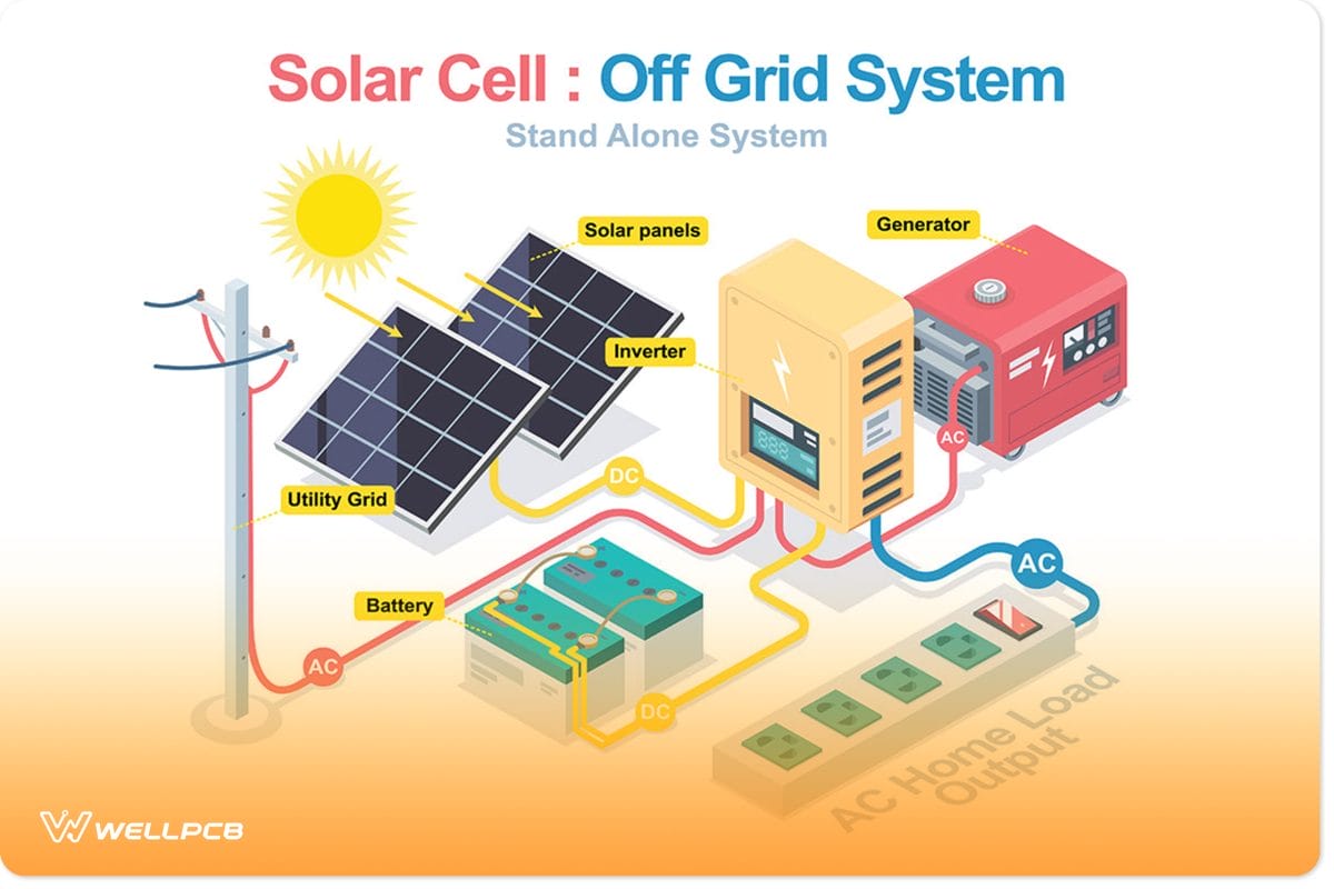
Solar
Solar inverters are system components of photovoltaic that are for off-grid and grid-connected systems. In other words, this type of inverter has unique functions made for photovoltaic arrays.
Power Grid
Also, another main application of inverters is on the power consumption and grid. The making of the grid-tied inverter is to feed the electric power distribution system.
solar cell system with a hybrid inverter
Conclusion
In summary, the above steps have shown that you can make an inverter circuit at home with the right components and input voltage. Here, we have provided a straightforward procedure for making an inverter and outlined the components required to build it.
In addition, it is advisable to test your inverter after building to ascertain its efficacy. Also, your eyes should be on inverter designs, the output power or power output.
Meanwhile, if you think these basic design steps are quite complex or want to explore more advanced designs, click here to get more clarification or support.


