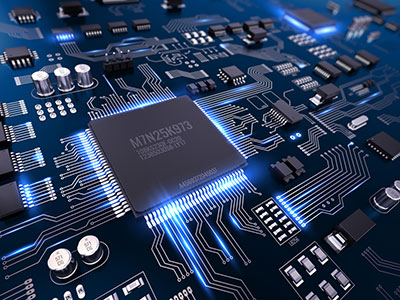
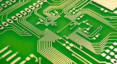
For PCBs‚ heat, generation is a significant challenge. Excessive heat affects the functions of the PCB and can damage its components. There should be effective heat dissipation to handle heat generation. However‚ as parts get smaller everyday‚ excess is becoming a challenge. Heat dissipation occurs naturally through the board itself.
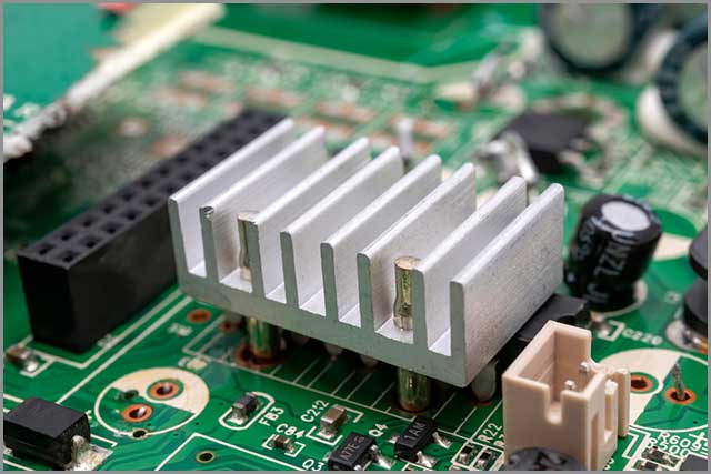
When natural dissipation is not sufficient‚ dissipation can also occur by forced means. To force excess‚ you can use heat sinks (fans‚ radiators)‚ air coolers and more. It is going to lead to better PCB trace current capacity.
Contents
- 1 Perform a Thorough Visual Inspection of your PCB Board
- 2 Infrared Camera
- 3 Thermal Analysis
- 4 Electrical Power Usage
- 5 Convection in PCB
- 6 Using Online Heat Sink Calculators
- 7 Using Temperature Sensing Diodes
- 8 Use Datasheets/tables for Common PCB Components
- 9 Weighted Volume Effective Thermal Conductivity Method
- 10 PCB Trace Temperature Rise
- 11 Summary
Perform a Thorough Visual Inspection of your PCB Board
When designing a PCB, you should pay attention to maximizing heat dissipation. Proper dissipation of heat is essential in giving a long life to your PCB. It will also ensure that the PCB is functioning correctly.
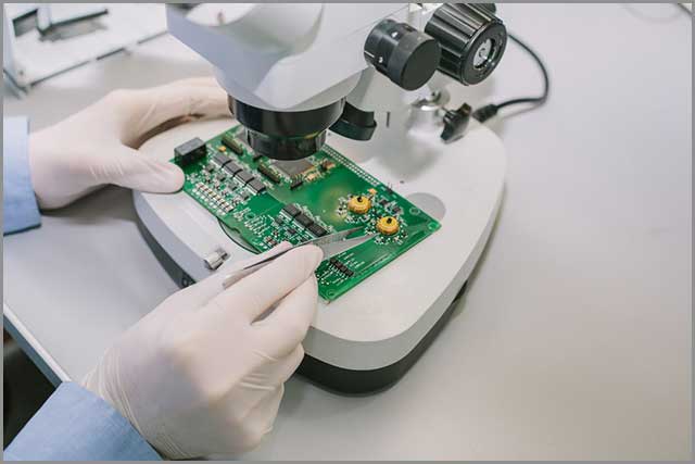
It is the quickest‚ simplest way to inspect your PCB board. First‚ you need to turn off the power to the PCB. When it is in off stat, you can continue to investigate. You can try touching the surface of the integrated circuits to check if it is overheating. If your board short circuited‚ you can check for burn spots. These are the brown marks you will see on the usual green board. You can use this burn spot to pinpoint where the PCB design is overheating.
Infrared Camera
There is only so much you can see with your naked eyes. To discover where high heat is generating‚, you can use an infrared camera as well.
Infrared cameras are also called thermal imagers. These cameras make thermal heat visible. You can use this to identify the exact locations that generate excessive heat. These can give you an accurate measurement of heat. The infrared camera uses lenses that can focus down to 20µm lines. Some cameras create a layer by layer thermal image with a visible wavelength image.
You can use infrared cameras to get the thermal image of a good PCB along with the overheating one. Comparing the two images will help you locate excess heat generating areas on your PCB. An infrared camera is invaluable in analyzing a PCB is the capacity to dissipate heat. It is an excellent way to manage the PCB trace current capacity.
Thermal Analysis
During thermal analysis, the PCB undergoes rigorous analysis in varying temperatures. This analysis helps in measuring how the PCB will behave in a given environment. Environmental heat is a factor that can profoundly affect the PCB. Most PCBs operate in high tech environments.
So‚ it is extra important to see how your PCB will work in varying environmental conditions.
When designing the PCB‚, you can use thermal analysis to simulate various conditions. This technique helps in identifying thermal problems and heat dense areas. You can effectively handle these issues in the designing phase itself. Thermal analysis is essential in optimizing your PCB even before construction.
Electrical Power Usage
The main reason for heat generation in PCBs is the heating up of components mounted on the board. When considering electric power usage‚, two factors affect heat dissipation. Those are power distribution on the PCB and power consumption per unit area. Proper allocation of components across the PCB is essential in increasing heat dissipation.
In the horizontal direction, ‚ arrange high-power usage devices close to the edge. In the vertical direction‚ you should agree on high-power usage devices close to the top of the PCB. High-power consumption and high heat generating devices should be close to cooling devices. It is also important to place high heating components away from edges or corners.
That is unless you have a cooling device to cool the high heating device. High heating devices can affect lower heating devices and heat them. If adequately arranged, this effect will not happen. Devices consume more power to be evenly distributed along with the PCB area. By avoiding high power density areas‚, you can maintain a consistent surface temperature. It is an excellent way to have good PCB trace current capacity.
Convection in PCB
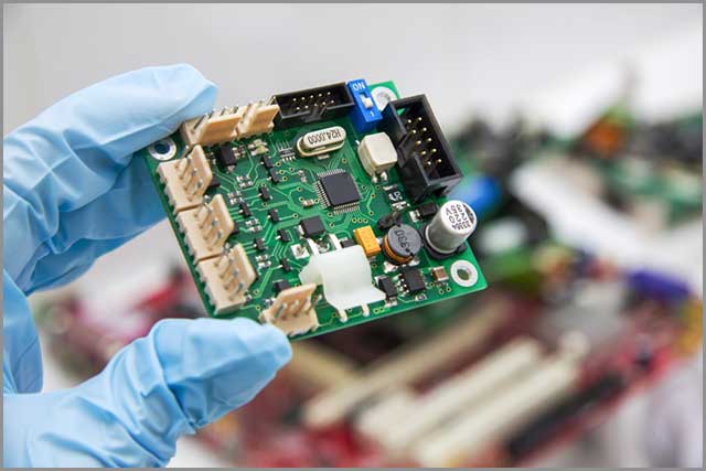
PCB generally has several components mounted on it. All these components heat up during operations. To keep operating effectively, the PCB needs to dissipate this heat. Heat dissipation can occur automatically or by forced means like implementing heat sinks. Convection and radiation are two methods by which dissolution can occur. Convection is the transferring of heat from component to component.
Radiation is a heat dissipation that does not require any medium. Your PCB should consist of high absorptive materials that increase pollution. Increasing the temperature of radiators and decreasing the temperature of absorbers increases radiation. Once convection and radiation are high‚, it affects PCB is heat dissipation capacity favorably.
Using Online Heat Sink Calculators
Online heat sink calculators are software designed specifically to calculate heat sink. There are various heat sink calculators intended for different tasks. You only need a few parameters to operate these calculators. For example, some calculators calculate maximum temperatures a device can withstand. You need to provide parameters such as maximum ambient temperature and power applied. Then the calculator will calculate the maximum temperature and control a device can handle.
Some similar calculators calculate PCB trace current capacity‚ heat sink size, and more. These are available free of charge, and you can use them to optimize your PCB.
Using Temperature Sensing Diodes
You can also use inexpensive semiconductor diodes to measure heat dissipation. Some examples of diodes you can use are 1N914‚, 1N4148, and 1N400X. These diodes won’t give an exact measurement. But‚ they can still give you an estimate on the generation of heat through the PCB. You can mount the diode on components such as transistors‚ transformers, and batteries. To monitor temperature‚, you need to use sensors with linear temperature characteristics. And diodes like the above mentioned are a good choice for sensing temperature.
Use Datasheets/tables for Common PCB Components
Datasheets are like instruction manuals made by engineers for engineers. These contain exact information on how a part works. When you use a datasheet‚, you need to make sure that it is the latest datasheet on the given element. Referring to the newest datasheet is essential to make sure that you are not running into any errors.
You can find datasheets with detailed specifications for almost every part. It includes the thermal properties of nearly every component. Datasheets are useful to get an idea of the heat generation of each element of the PCB. It can help manage PCB trace current capacity. You can use this estimation to determine how to optimize the PCB for heat dissipation.
Weighted Volume Effective Thermal Conductivity Method
In PCBs‚, the failure of one component is enough to fail the operability of the whole board. Thermal conductivity among PCB components is not constant. So‚ it’s essential to maintain an excellent thermal design to make sure that the PCB can operate in high temperatures. The PCBs weight/unit area refers to the thickness of the copper cladding on the laminated board. For efficient thermal conduction, there should be a continuous copper path. Thermal conductivity is also affected by the number of vias in the PCB.

PCB Trace Temperature Rise
Traces are the paths that carry electricity around the PCB. These traces, too, can overheat. You can calculate the PCB trace temperature rise using P=I^2R, an equation derived from Ohm is the law.
There are two factors affecting temperature rise in PCB traces. Those are PCB trace current capacity and trace width. PCB trace current capacity is the maximum current that a bit can carry. Higher winds will need a thicker trace width.
Summary
We hope you found this article helpful. To give you a rundown‚ excessive heat can affect the functions of the PCB. Therefore‚ it is essential to identify spots generating excessive heat. If the PCB fails to dissipate heat properly‚ the entire board will fail. That is why you need to be aware of how to design your PCB and test it for optimal heat dissipation. It can be a rigorous process and will require testing‚ testing, and more testing.
We‚ at WellPCB, have experience in manufacturing PCBs. We can give you precisely what you need. Why wait when you could have our expert team manufacture your PCB today?
Contact us to get started!
