Contents
What is PCB Welding
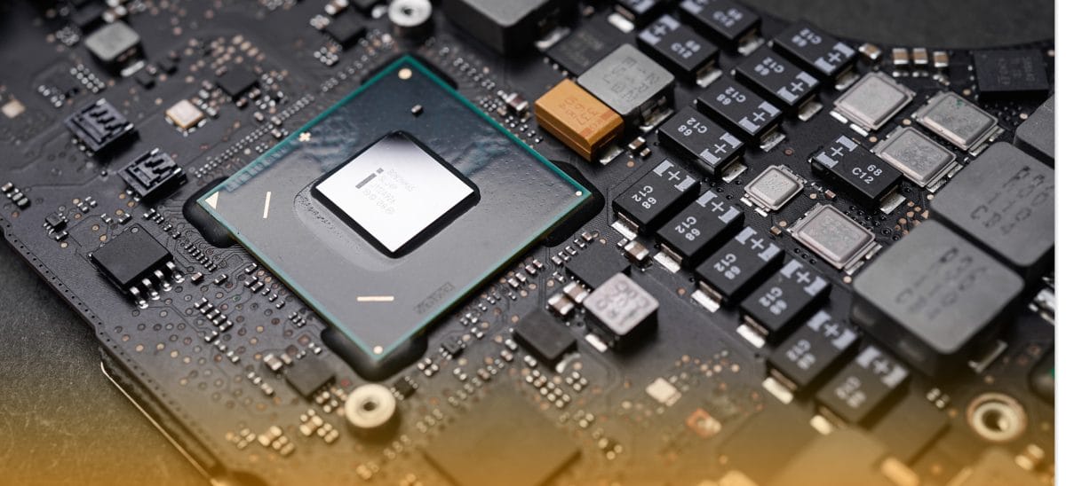
PCB welding is the process of fixing one or more electronic components on a printed circuit board using solder. After being heated, the solder melts and then hardens, ensuring the electronic components stay in their places. This process creates strong electrical and mechanical connections, attaching parts securely while efficiently transmitting signals.
“PCB welding” and “PCB soldering” are often used interchangeably. This is because soldering is the primary technique used. The melting point of solder metal is lower than that of the PCB parts and materials being used. So, the solder can melt and flow to create connections without damaging the heat-sensitive parts or the PCB itself.
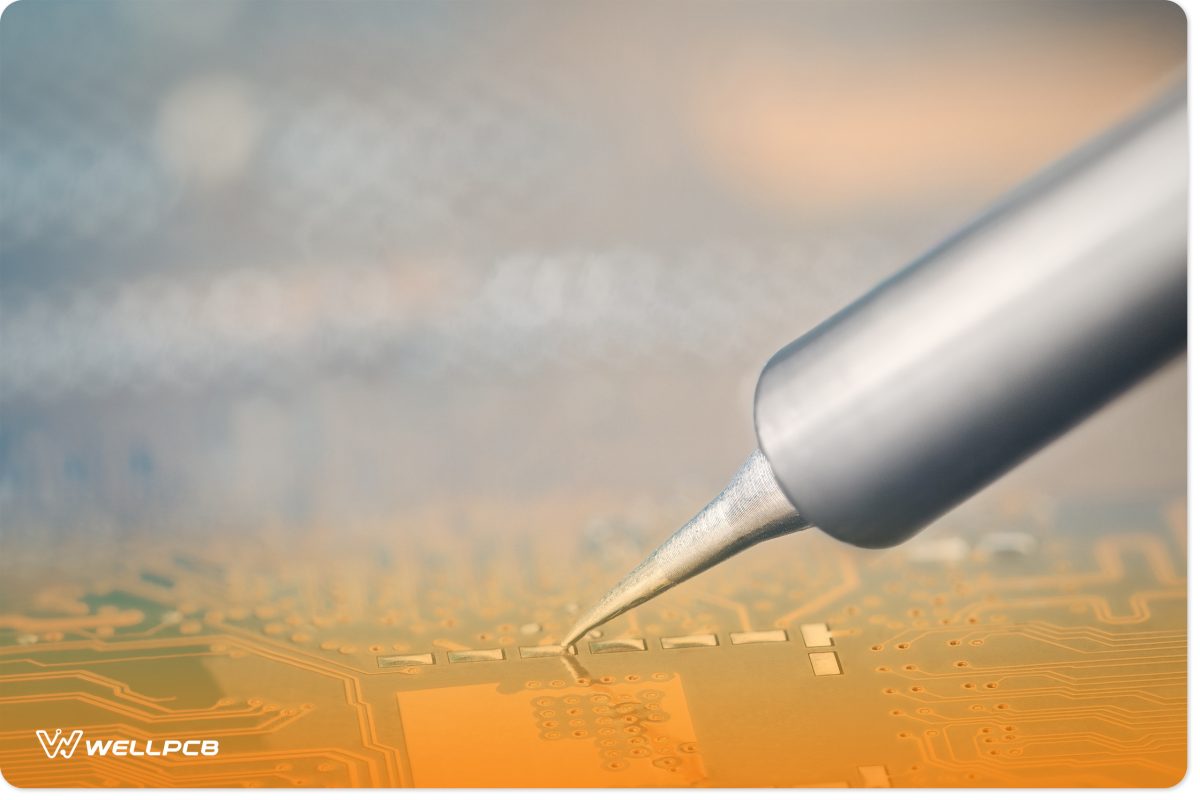
PCB welding can involve various techniques, such as hand soldering for prototypes and repairs, or automated techniques like wave soldering and reflow soldering for large-scale manufacturing. Each technique requires precise temperature control, proper tools and attention to detail to achieve high-quality results.
Methods of PCB Welding
PCB welding is classified into two main methods: hard and soft soldering. The optimal method depends on factors like the components to fix and the level of heat they can withstand.
Hard Welding
Hard welding, also known as high-temperature soldering, involves joining two metal components using a filler metal that melts at temperatures exceeding 840°F (450°C). The molten filler flows into the gaps between the components, creating a durable and reliable connection once cooled.
This method is better suited to applications requiring strong joints that are capable of withstanding high mechanical stress and heat.
Silver Welding
Silver soldering is a type of hard welding that uses a silver alloy as the filler metal. This method is valued for its ability to produce clean, strong joints. It’s suitable for manufacturing small components, repairing tools and periodic maintenance tasks.
However, silver soldering is not ideal for filling large gaps. To achieve the best results, use a flux specifically designed for silver soldering to promote proper bonding and minimize oxidation.
Braze Welding
In brazing, two components are connected using a liquid metallic filler, such as brass or bronze alloy. The filler flows into joints through capillary action and solidifies to create a strong bond.
This method relies on atomic bonding and diffusion to achieve its durable connections.
Soft Welding
Soft soldering involves joining tiny components using low-melting-point alloys like tin-lead or lead-free solders. This technique is ideal for placing delicate parts on PCBs without causing thermal damage.
The process typically occurs at temperatures between 356°F and 446°F (180°C to 230°C), making it safe for sensitive electronics. Essential tools include a temperature-controlled soldering iron and flux to clean and prepare the joint surfaces.
Tools Required for PCB Welding
It’s crucial to have the right tools at your disposal to successfully weld PCBs. In this section, we’ll walk through the essential tools you require and how they contribute to a clean, efficient welding process.
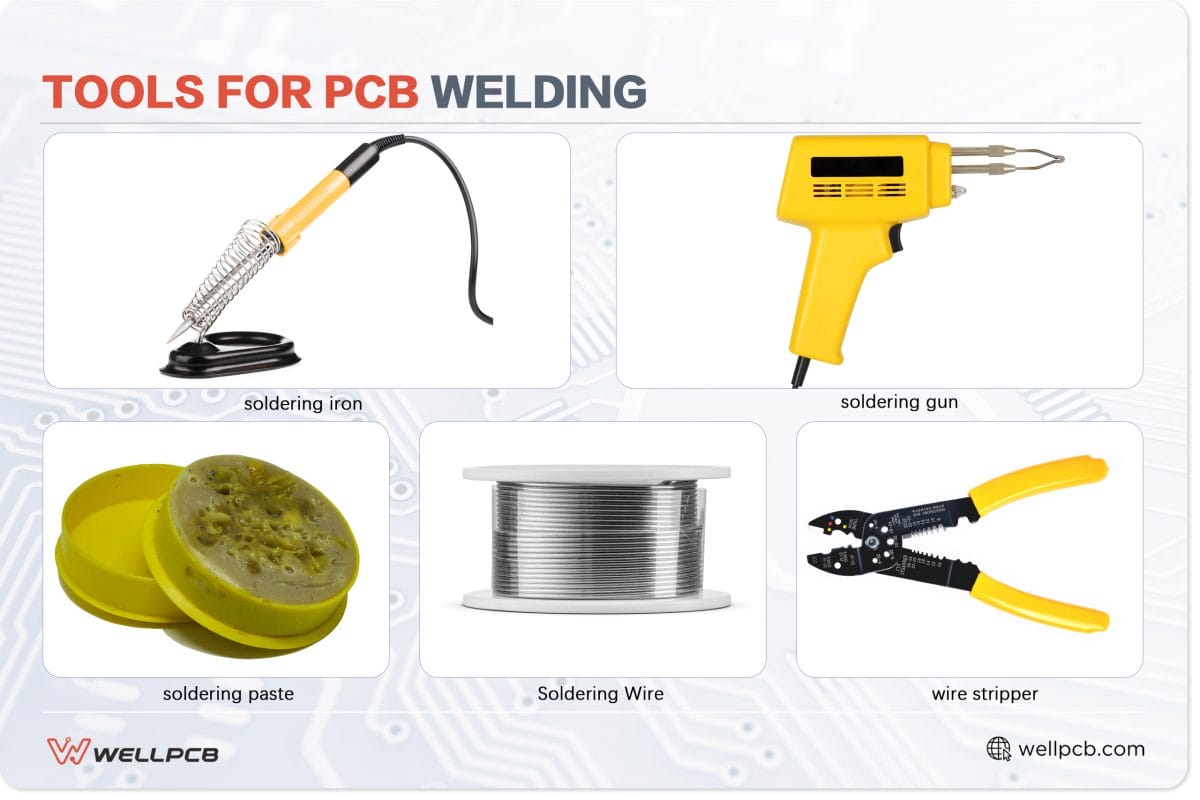
Soldering Iron
A soldering iron is a key tool for welding or soldering, providing the heat required to liquefy solder and create reliable connections between electronic components. It works by melting soldering wire, allowing it to flow into the gaps between two connections. As the solder cools, it forms a secure bond.
For most electronics projects, a soldering iron with a power capacity of between 15W to 30W is ideal. This power range is sufficient for delicate components without the risk of overheating.
However, if you’re working with heavier components, such as larger cables or heat-resistant parts, it’s best to use an iron with a higher power capacity. 40W or more will generally meet the needs of these tasks.
Soldering Flux and Paste
Soldering flux and paste are essential for achieving clean, strong solder joints. Flux is a chemical compound applied to the PCB and components before soldering. It cleans oxidation, promotes better heat transfer, and prevents the formation of unwanted residues during the soldering process. It helps the solder flow smoothly, ensuring it adheres well to the pads and leads.
Soldering paste, which combines flux with solder in a paste-like consistency, is commonly used in surface-mount soldering or for precise application in areas with small components.
When applying flux or paste, it’s important to use just the right amount. Too much can cause excess residue, while too little can lead to weak connections. After soldering, any remaining flux should be cleaned off to prevent corrosion or long-term damage to the PCB.
Soldering Wire and Wire Stripper
The soldering wire is a critical component for forging strong electrical connections between your PCB and components. The wire consists of a metal alloy, typically a combination of tin and lead (though lead-free alternatives are also available), which melts when heated by the soldering iron to form the solder joint.
The diameter of the wire varies. Thinner wire is ideal for delicate components and tighter spaces, while thicker wire is used for larger connections or through-hole components. It’s important to choose high-quality soldering wire with a flux core to ensure optimal solder flow and joint quality.
A wire stripper is equally important for preparing wires before soldering. This tool is used to remove the insulation from the ends of the wires, exposing the conductive metal inside without damaging it. Proper stripping is essential for ensuring good electrical contact between the wire and the printed circuit board.
Be sure to select a wire stripper with adjustable settings to match the thickness of the wire being stripped. And, always handle the tool carefully to avoid nicking the wire, which can weaken the connection.
Tips and Best Practices for Soldering
Follow these tips and best practices to ensure high-quality, reliable solder joints. As a result, you’ll avoid common pitfalls during the process.
- Use heat sinks: Sinks help dissipate excess heat and prevent damage to the parts. You can use tools like alligator clips or dedicated heat sink clamps to protect nearby components while maintaining effective soldering temperatures.
- Keep the soldering iron tip neat and clean: An excellent iron tip will ensure better heat conduction and result in an improved joint. To clean the end, use a damp sponge or brass wire cleaner and re-tin it to prevent oxidation.
- Ensure correct soldered joints: Proper soldering involves applying just the right amount of solder to create a strong connection without forming cold joints or excess blobs. The joint should have a smooth, concave shape, fully covering the connection points for reliability and conductivity.
- Solder tiny electronic components first: Start with small components like diodes, resistors and jumper wires. This makes it easier to access and position them on the PCB without obstruction. This approach also prevents accidental displacement of larger components while working on finer details.
- Solder sensitive electronic components last: Delicate components, such as semiconductors, MOSFETs, CMOS, ICs and microcontrollers, should be soldered after other parts. This is to minimize their exposure to prolonged heat. Using lower heat settings and heat sinks for these components can further reduce the risk of damage.
- Work in a well-ventilated area: Soldering generates fumes that can be harmful if inhaled over extended periods. To protect your health, always solder in a well-ventilated space or use a fume extractor to minimize exposure to potentially toxic vapors.
Ensuring that your soldering process aligns with established PCB assembly standards is vital for producing high-quality, durable connections. These standards, which are defined by organizations such as IPC (Institute for Printed Circuits), outline precise requirements for solder joint quality, component placement, and soldering materials. By following these guidelines, you can prevent common issues.
Common Problems of Printed Circuit Board Welding
Welding issues can arise at various stages of printed circuit board production, from design to manufacturing. These problems not only increase costs but can also reduce manufacturing yields and cause significant delays in delivering your product from concept to completion.
Many of these challenges stem from errors in the design or manufacturing process. Luckily, they are avoidable with the right tools and techniques.
In this section, we will explore common soldering problems, including those caused by manual soldering techniques and manufacturing faults.
Issues Caused by Soldering Manually
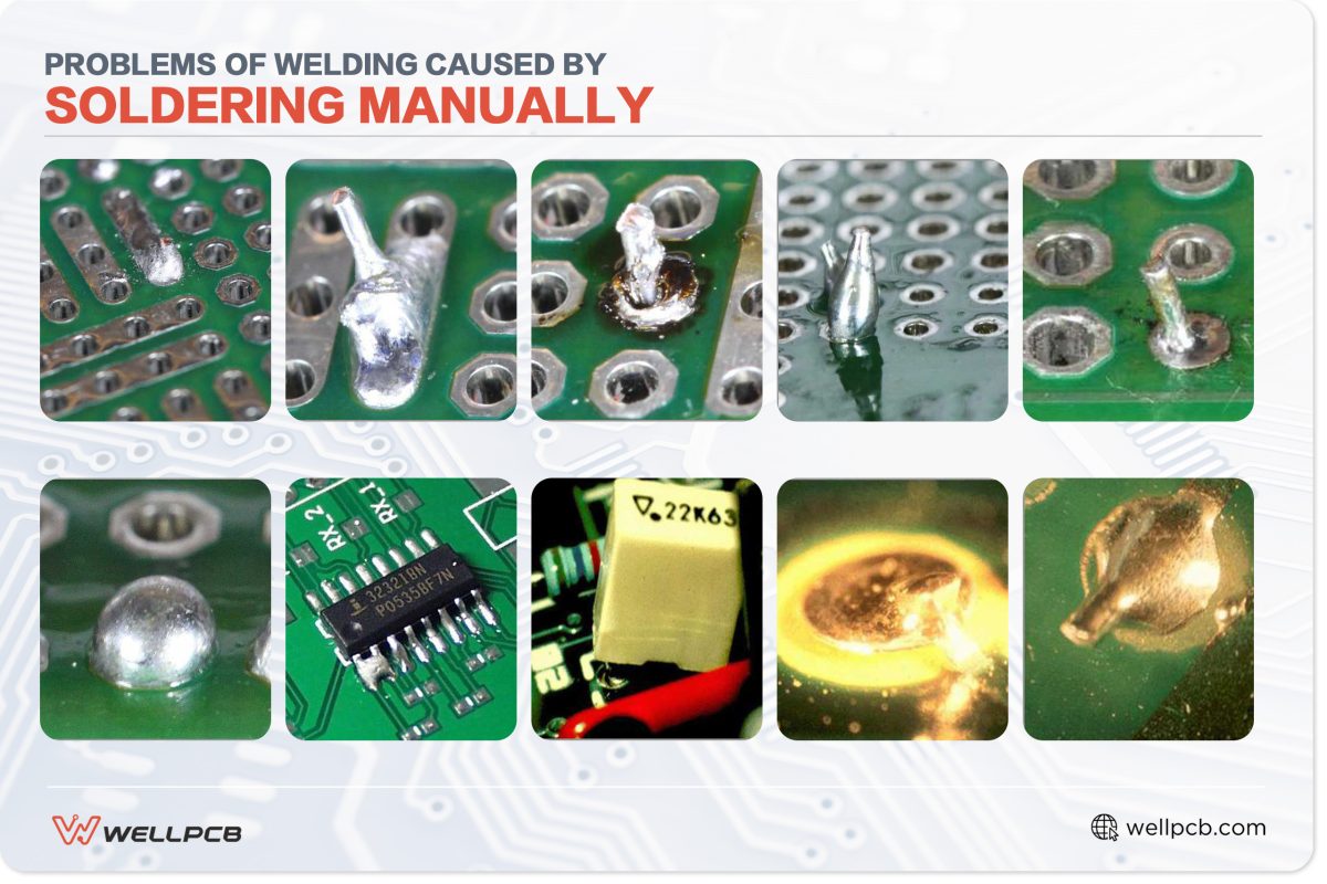
Manual soldering can be a precise and effective method, but it often introduces challenges that can compromise the quality of your PCB. Below are some of the most common problems encountered during manual soldering, along with explanations of how they occur.
- Disturbed joint: A disturbed joint happens when the soldered connection is moved before it has fully cooled and solidified. This results in a rough, uneven surface that weakens the joint and compromises electrical conductivity.
- Cold joint: A cold joint occurs when the solder doesn’t reach the proper melting temperature, creating a dull, lumpy connection. This weak joint can cause intermittent connectivity issues or complete circuit failure.
- Overheated joint: Excessive heat can damage the PCB or the component being soldered, leading to scorched pads, lifted traces or damaged components. Overheated joints may also exhibit poor solder flow and reduced reliability.
- Insufficient wetting: Insufficient wetting happens when the solder fails to spread properly over the surfaces being joined, often due to inadequate heat or oxidation. This can result in a weak bond that lacks sufficient electrical contact.
- Starved solder: Starved solder refers to an insufficient amount of solder applied to the joint, leaving gaps or weak connections. This issue often leads to poor mechanical stability and unreliable electrical performance.
- Too much solder: Using excessive solder can create messy, oversized joints that may bridge connections or cause short circuits. While it may appear secure, too much solder can actually lead to defects and increased risk of failure.
Issues Caused by Manufacturing
Manufacturing defects in soldering can arise due to errors in automated PCB assembly processes or poor quality control during production. These issues often compromise the functionality and reliability of the circuit, potentially leading to costly rework or even product failure.
Below are some of the most common soldering problems caused during manufacturing, along with explanations of how they occur.
- Solder bridge: A solder bridge occurs when excess solder creates an unintended connection between two adjacent pads or traces. This can result in short circuits, disrupting the functionality of the PCB and damaging components if not detected and corrected.
- Lifted components: Lifted components are a result of poor adhesion between the component and the PCB during soldering. This defect often occurs when solder paste is improperly applied or excessive heat causes the component to move or detach during reflow soldering.
- Lifted pads: These happen when a pad separates from the PCB substrate, often due to excessive heat, improper handling, or poor-quality materials. This can lead to open circuits or difficulties in repair, as the affected pad may no longer support a connection.
- Solder balls: Small, unintended spheres of solder form on the PCB surface, often caused by excess solder paste or improper reflow temperatures. These balls can create electrical shorts or reduce the overall reliability of the circuit, especially in high-density designs.
Techniques To Troubleshoot Welding Problems
Troubleshooting PCB welding issues requires a clear understanding of the root causes and the right techniques to fix them. By addressing issues, you can restore the functionality of your circuit while minimizing the risk of recurring defects.
Below are practical techniques for repairing common PCB welding problems and preventing future issues.
- Repair disturbed joints: Reheat the soldered area using a soldering iron while keeping the components steady until the solder solidifies. Ensure no movement occurs during cooling to create a smooth, reliable connection.
- Restore cold joints: Fix this by reheating the solder to the correct temperature and allowing it to flow properly. Adding a small amount of fresh solder can improve heat transfer and create a stronger bond.
- Repair overheated joints: Carefully remove the damaged solder and inspect the component and pad for damage. Apply fresh solder while using appropriate heat levels to avoid further issues.
- Fix insufficient wetting: Address insufficient wetting by cleaning the surfaces to remove oxidation or residue. Then, reheat the joint to improve solder flow. Use flux to aid solder adherence for a more secure connection.
- Repair starved solder: Add a small amount of solder to the joint while ensuring it spreads evenly over the connection points. Avoid overheating to prevent damaging the components or PCB pads.
- Correct too much solder: Excess solder can be removed using a desoldering pump or solder wick. Reheat the joint to apply the appropriate amount of solder, ensuring a clean and precise connection.
- Repair solder bridges: Remove the excess solder forming the bridge using a solder wick or desoldering pump. Reapply solder carefully to avoid bridging adjacent pads or traces.
- Minimize reheating components: Work quickly and efficiently, using proper soldering techniques and ensuring adequate preheating of the PCB if needed. Heat sinks can also protect sensitive components during rework.
- Restore lifted pads: Carefully reattach pads to the PCB substrate using adhesive if possible. Reconnect the pad to the circuit by soldering a thin wire or jumper to the nearest trace.
- Prevent solder balls: Avoid solder balls by using the correct amount of solder paste and maintaining precise reflow temperatures. Ensure the PCB is clean and free of contaminants before soldering.
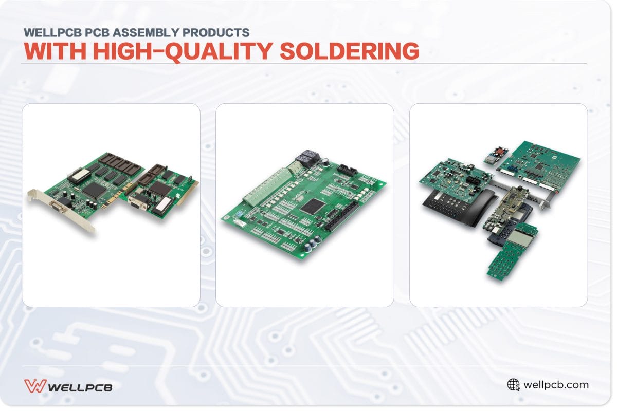
Turnkey services offer a dependable solution if you want to avoid the complexities of manual soldering or the risks associated with manufacturing defects. With turnkey PCB assembly benefits such as streamlined production, cost efficiency and high-quality results, WellPCB handles every step of the process, delivering expertly assembled PCBs tailored to your exact specifications.
Conclusion
Mastering PCB soldering requires a blend of the right tools, techniques, and troubleshooting strategies to ensure high-quality results. Whether you’re a professional tackling large-scale manufacturing or a DIY enthusiast perfecting a personal project, overcoming welding challenges is key to creating reliable circuits.
At WellPCB, we understand the complexities of PCB welding and are here to support you at every step. With our expert PCB manufacturing services and PCB assembly services, we ensure that your designs are executed with precision and care.
Whether you need assistance with troubleshooting, high-quality components or full-scale PCB production, WellPCB is your trusted partner. Let us help bring your projects to life with professional-grade solutions tailored to your needs.