There are several different ways of controlling the speeds of DC motors. However, one of the most preferred and simple ways is by using a Pulse Width Modulation (PWM) circuit. The PWM (Pulse Width Modulation) is a technique used in driving inertial loads for a long time. The use of pulse width modulation in controlling motor drivers comes with several advantages.
But perhaps, the most significant advantage is that since the transistor is either fully “OFF” or “ON,” the power loss in the switching conductor remains small. This article discusses how to go about designing a PWM circuit. Here, there will be a discussion of important issues, such as effectively cutting electric signals into discrete parts as a means of reducing the power of electronic signal transmission.
Contents
Professional Introduction To PWM Circuits
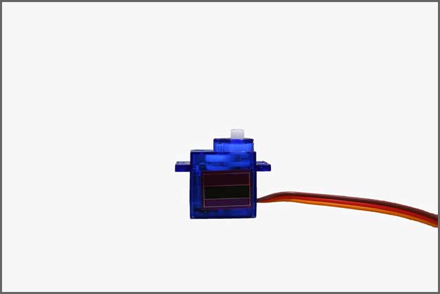
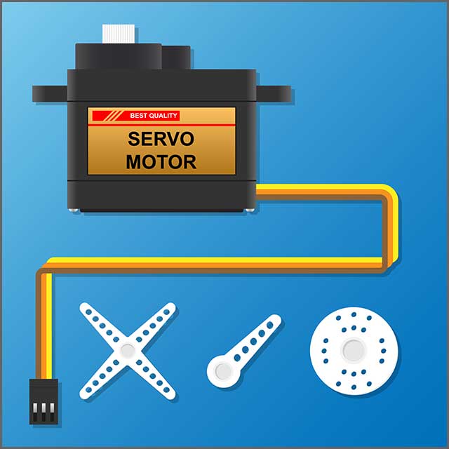
Pulse Width Modulation (PWM) is a term used in the description of a type of digital signal. Pulse width modulation finds use in plenty of applications such as sophisticated control circuitry. A standard method whereby PWM sees a lot of use is in controlling the dimming of LEDs and controlling the direction of servo motors.
Pulse width modulation circuit works by reducing the average power during the transmission of electric signals. It does so by separating signals into discrete parts or samples. As mentioned earlier, there are plenty of advantages and uses in telecommunication, voltage regulation, servo motor control, digital circuits, and motor speed control, among others.
Pulse width modulation circuits are a top choice for many users based on the fact that they don’t make a lot of noise when in operation. Unlike analog signals that emit some sound when in process, pulse width modulation circuits are noise immune and highly efficient. Better yet, pulse width modulation circuits are economical and don’t require a lot of space. Pulse width modulation circuits aren’t tricky or tasking to construct. The components needed in the manufacture of these circuits are easy to assemble.
Additionally, the steps to follow in the manufacture or production of pulse width modulation circuits are super comfortable, unlike the design of other courses. Pulse width modulation circuits are easy to convert back to analog circuits using minimum hardware.
Duty Cycle, Frequency, And Pulse Width In A PWM Circuit
lDuty Cycle
As mentioned earlier, a pulse width modulation signal stays on for a specific time and then goes off for the rest of the time. It operates on an “ON” and “OFF” basis. An aspect that makes the PWM signal more useful and unique is the fact that it can be set to stay on for a particular time by controlling the duty cycle. The percentage or ratio of time that the PWM signal remains on time or HIGH is known as the duty cycle.
In case the signal remains ON, then it is in a 100% duty cycle. But in case it is always off, then it is a 0% duty cycle. The formula for calculating the duty cycle is as below:
Duty Cycle = Turn ON time/ (Turn ON time + Turn OFF time)
Frequency of PWM
The frequency of a pulse width modulation circuit determines the speed or rather how fast a PWM takes to complete one period. One Period is full or complete ON and OFF period of a pulse width modulation signal. Normally, the pulse width modulation signals that a lot of microcontrollers generate are around 500 Hz. Such frequencies find a lot of use in high-speed switching components such as converters and inverters.
However, not all applications need high frequency. For instance, to control a servo motor, you’ll need to produce PWM signals with a frequency of about 50Hz. To put it in simple terms, how fast the pulse width modulation signal turns on and off gets decided by the frequency of the PWM signal.
Pulse width in a PWM Circuit
A PWM circuit consists of a Pulse Width (PW). Pulse width, by definition, is the elapsed time or time taken between the rising/high and falling/low edges of a single pulse. Pulse width is the duration of another signal, usually a carrier signal used in transmission. To make such measurements accurate and repeatable, 50% of the power level gets used as reference points.
How To Build A PWM Circuit
Building a PWM circuit is not a difficult task as such. The following are some of the materials needed to make a PWM circuit. Glossy Paper
- Copper clad board
- Acetone
- Ferric Chloride
- LASER Printer
- Scissors
- Marker Pen
- Plastic container
- Sandpaper
- Safety gloves
- Saw
- Latex gloves
Step 1: Designing the circuit
Begin by designing the schematic diagram in PCB design software. You can use design software such as Kicad, Express PCB, Dip Trace, NI Multism, or Altium Designer. EAGLE PCB Design Software is the best option.
Step 2: Designing the PCB Layout
After you complete designing the schematic diagram, now it’s time to develop the PCB layout, preferably using the Eagle EDA tool. After you finish, take a print out of the manufacturing of PCBs, there are high chances of layout failures, which can go a long way into negatively affecting the final product’s functionality. There are several PCB layout on the glossy paper. Here, use a LASER printer only. Components needed here include the following:
- Header (2.54mm)
- PCB: FR4 Glass Fiber
- Screw Terminal Block
- Capacitor – 0.1 uF (104)
- Resistors
- 1N5403 – Diode (3Amps)
- TLP250 – Gate Driver
- IRFP460 – Power MOSFET
Step 3: Soldering Process
To drive the power MOSFET, use an IC gate driver. But again, TLP250 IC is suitable for the gate driver circuit of IGBT and power MOSFET. You can use the PWM controller to control the brightness levels of an LED or even use it as an LED driver. The PWM controller also works or performs the same roles as a PWM dimmer.
Step 4: MOSFET Power Dissipation Calculation
The fourth step involves the calculation of power dissipation. The following is a formula of calculating power dissipation:
P = R X I2
P = Rds (ON) X I2
Here,
P = Power
I = Current
Rds(ON) = Drain-Source On-State Resistance
Step 5: Maximum Power Dissipation minus Heatsink
Power dissipation is the maximum power dissipated by the MOSFET under specified thermal conditions. The fifth step to building your PWM circuit involves the calculation of maximum power dissipation without a heatsink. The calculation of power dissipation is simple. Power dissipation is calculated by taking the junction temperature and subtracting the ambient temperature then dividing it by the maximum junction to ambient.
Pd = Tj (max) – TA
ROJA
Step 6: Interfacing of the PWM Driver
This is the final step towards having your PWM circuit. To interface or rather complete your PWM driver, you will need jumper wires, a PWM driver, an Arduino UNO board, a DC motor, SMPS, and a 10k potentiometer.

Things To Note
PWM circuit design can turn out to be a daunting task, especially if you fail to follow instructions carefully. You may notice that in reality, things will be a little different from what you find in books or the internet. To be on the safe side, you need to factor in several issues. For instance, you have to ensure that you have in place all the materials you need.
Also, you need to ensure that you follow all the steps from the beginning to the end, as indicated. You also have to factor in matters to do with safety. Ensure that you work in a clean and safe environment. Also, you need to be familiar with calculations as you may have to calculate essential aspects such as power dissipation, resistor wattage, and the use of microcontrollers, among others.

Application Area
PWM circuits find use in a wide variety of applications. Apt examples of where PWM controllers find use include the following:
- Used for controlling speeds of DC motors
- They find use in controlling the brightness of LED light strips and LED lights
- Used for tone generation
- They also find applications in for DC power heaters
- Used in DC powered components
Do You Want To Set Up A PWM Controller? You Can Contact Us
Setting up a PWM controller can turn out to be a difficult task. A majority of people find it hard when it comes to setting up PWM controllers. Are you finding it hard to set up a PWM controller? Don’t worry. We at WellPCB are here to assist you. Don’t suffer in silence when we can help. Wne understand every aspect to do with PWM motor controllers. Let us set everything up for you while you sit and relax. Depending on your use, we will set the load for you, connect all the wiring to avoid shorts, and calculate maximum power dissipation for your PWM controller.
Conclusion
As noted earlier, controlling the speed of DC motors is achievable in many ways. However, the use of Pulse Width Modulation is the best and most trusted method. There are plenty of advantages associated with the use of pulse width modulation in controlling the speeds of DC motors. Some of them include small power loss and constant motor voltage. Building a PWM motor can be a frustrating exercise, especially if you do not adhere to all the instructions. If you are finding it hard to develop and set up a PWM controller, you can contact us for assistance. We are the best professional PWM designers with decades of experience and professionalism.


