Contents
What are SMD Components?
Surface mount devices are electronic components placed directly onto the surface of a PCB. The technology used to mount SMD components in this manner is surface mount technology (SMT).
Before SMT emerged in the 1960s, there was a through-hole technology construction method. It involves using lead on the electronic components to insert them into a hole drilled in a PCB.
SMD electronic devices are smaller than their through-hole counterparts, meaning many can fit on both sides of the board.
So this allows for a much higher component density and more connections per component.
Other advantages of SMT components over through-hole counterparts include:
- First, easy manufacturing process
- Second, the solder of an adjacent SMT component is not easy to displace during the soldering process.
- Finally, autocorrect small errors in component placement.
However, through-hole electronic components also have their advantages, including better stability. For that reason, you can combine the two technologies for better functionality.
Types of SMD Components
Based on various factors, SMD components can be active or passive. These two types of SMD components differ in terms of:
- Nature of energy source
- Functionality
- Power gain
- Flow of current
- The requirement for an external source
Active Components
These are active devices that:
- Deliver power or energy to the circuit.
- Produce energy form of voltage current.
- Capable of providing power gain.
- Can control the flow of current.
- Require an external source for the operation.
Examples include transistors, diodes, integrated circuits, and SCR.
Passive SMD Components
Passive components are devices that:
- First, utilizes power or energy from the circuit
- Then, store energy in the form of power or circuit
- Besides, they are incapable of providing power gain
- Also, it cannot control the flow of the current
- Finally, do not require any external source to operate
The main examples are monolithic ceramic capacitors, thick film resistors, and tantalum capacitors.

Circuit Board Components Identification
We will show you how to identify SMD components in a circuit board. Given the many SMD components, we will review the most commonly used ones.
Chip Resistors (R)

Chip resistors are common SMD packages on PCB electronics. The first two or three digits on the body of a chip resistor indicate the resistance value.
The last digit is a multiplier with a power of ten. “105” is equivalent to “1 M Ω,” and “672” is equivalent to “6.7K Ω.”
Network Resistor (RA/RN)
Network resistor chips feature high-grade ceramics with metal electrodes on either end of the chip. The chips consist of a group of resistors that have similar properties.
It’s the same as identifying chip resistors.

Ceramic Capacitors
An interlocked ceramic dielectric block has metal electrodes. A layer of plated tin covers the inner electrodes, linked to the end terminations (NiSn).
In general, PCB manufacturers utilize SMDs with MLCC. In addition to the COG (NPO) type, there are three more varieties of MLCC: the X7R and Y5V types.

Diode (D)

The pin voltage regulation of an SMD diode is similar to the general-purpose SMD diodes in terms of terminals.
Observing the casing, you can identify the positive and negative poles of SMD diodes. However, the marks wear out, so we use a multimeter for identification.
LED
When a current travels through a Semiconductor Crystal, it generates light. The individual product manufacturing guideline determines the polarity of an SMD LED. SMD LEDs are available in different sizes. Like most SMD components, you can identify them in size and numbers.

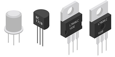
Transistors (Q)
The most common surface mount device transistor packages are SOT-23 and SOT-223 (larger). The first two letters on the transistors identify them, regardless of the manufacturing code.
Inductors
SMD inductors have +ve reactance, and they come in a variety of sizes and shapes. You can see their values on the casings of the components.
The value is in standard two-digit and exponent fashion. For example, 100 µH would be 101 – 10 x 10^1, and 100 would be 10 x 10^0.

SMD Transformers
In general, a wire wraps around the SMD transformer’s toroidal core. The design includes surface-mount headers for PCB connectors.
The SMD transformer design is different from other types in many ways. It has unique voltage and current output, power rating, bandwidth, and more.
Crystal Oscillators (X)
Identifying SMD crystal oscillators is simple. If it is within an electrical circuit, you need to locate the position of the crystal oscillators.
On a computer motherboard, the label “XTAL” is written on top of the device, along with the frequency.
Fuse
SMD fuse helps in surface onboard circuit protection. The voltage rating is sometimes indicated by a voltage code letter. For example, in “F02G1R00A”:
F- fuse
02- Style
G- voltage rating
1R00-current rating
A- time delay rating

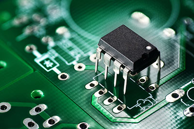
IC (U)
An integrated circuit (IC) is the most functional component of electronic products. Surface-mount packages for ICs come in various shapes and sizes.
The waffle pack holds large ICs such as plastic led chip carriers (PLCC) and quad flat packs (QFP).
Leadless ceramic carriers are the main surface-mount technology packages for IC.

Conclusion
Hopefully, we have made SMD component identification easier during the PCB assembly process. Please feel free to contact us with any questions on SMD components.