Contents
- 1 1. What is Through-Hole Technology?
- 2 2. Through-hole leads
- 3 3. Through-Hole Soldering
- 4 4. Advantages of Through-Hole Technology
- 5 5. Constraints Related to Through-Hole Technology
- 6 6. Surface Mount Technology (SMT)
- 7 What is the Difference Between SMT and through-hole PCB?
- 8 What are the Standards for Plated Thru-Hole Size?
- 9 Thru-Hole Assembly Design Considerations
- 10 Applications of Thru-Hole Technology
- 11 Thru-Hole PCB Manufacturers
- 12 Conclusion
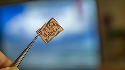
1. What is Through-Hole Technology?
It is a mounting technique where the leads and chips of electronic components are inserted through holes in the printed circuit board.
Here, these pins undergo soldering from beneath to pads on the opposite sides of the board. This technique is usually done by hand or sometimes by insertion mount machines.
This technology thrived well until the late 1980s, with the surface mount technology (SMT) capping it down.
With the surface mount’s introduction, the Through-Hole was expected to be obsolete.
Still, its numerous and distinctive advantages and reliability have stood the test of time.
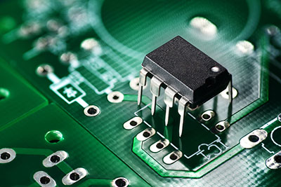
2. Through-hole leads
PCBs that use Through-Hole have wire leads that come in two types: radial or axial leads.
2.1.Axial
The axial leads are similar in shape to wire jumpers, and they protrude from the tip end of either boxed-shaped or cylindrical components of the PCB.
These protrusions will form almost a perfect geometrical axis of symmetry. Even though they protrude, it is not much above the PCB’s surface, making it flat if placed down.
Axial leads are commonly used to bridge short distances on a PCB while spanning point-to-point wiring that open space does not support.
2.2.Radial
The radial name comes from the parallel projection of the leads from the components to the surface board, and radial leads are in sync with the packages’ ends.
Before, they were identified because they took the shape of the radius of the cylindrical components that they protruded over, but the axial leads later nullified this definition.
Onboard, the radial components have a 90-degree angle formation with a lesser footprint than the axial leads.
Due to their parallel composition, they also have a plugin nature, making them a considerable choice for components requiring higher automation speeds.
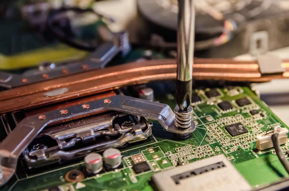
3. Through-Hole Soldering
Well, soldering is one of the necessary skills you need to venture into the electronics world. Knowing your way around a PCB board with what needs replacement and where is crucial.
However, much precision comes into place when it comes to repairing boards that use through-hole technology.
3.1.Advanced PTH
Assuming you have the necessary soldering skills at your fingertips, you could opt for the Advanced PTH technique.
Let’s dive and see some essential tips you need to learn.
1. Learn to control how the solder flows. This skill is the first thing you will learn, but you will get it right with time and practice.
2. Learn to use and control different tips of the soldering gun. That is because various applications require separate tips, and you should know how to use them.
3. Once you have decided on a gun to use, heat the lead and the pad and let the solder flow smoothly through the hole on the board.
4. Let the soldering iron cool. Then, you will have your connection ready.
5. You can use this technique when creating bridges between two Through-Holes.
3.2. Cleaning
Once you have performed your soldering, knowing how to clean it is crucial. What do we clean, some might ask?
When dealing with lead-free solder, you tend to mess up your PCB with flux.
This flux can be from the soldering iron itself or when you intentionally apply flux to avoid wrong connections. So, how do we go about this?
The best and recommended way is the use a small toothbrush that you dip or spray with isopropyl alcohol and brush the board.
But if you are working on many boards and risk having the flux dry on them, you could fill a crockpot with distilled water.
The distilled water will ensure that no impurities are within the circuit.
4. Advantages of Through-Hole Technology
The through-hole technology is impressive even though it has been there repeatedly, and newer technologies might replace it.
What reasons make it a preferred technology over the surface mount? Let’s examine the advantages of this technology for PCB designs.
4.1.Sturdy
Through-hole components are a real gold mine for their durability and effectiveness in products that require secure connections in their layers.
So, if you are working on a PCB board with this technology, you will notice that no matter what environmental stress you expose it to, the components will remain in contact.
Through-hole components are reinforced when they run through the board compared to SMT components that are only soldered on the PCBs.
With this aspect, they are commonly used in military and aerospace electronics since they can endure extreme variable conditions.
4.2.Stronger mechanical bonds
Through-hole technology works perfectly well for components that are heavier or bulkier in their composition.
It is considerable because they require stronger bonds mechanically in their PCBs, which ordinary Surface Mount Technology will not offer to these electronics.
4.3.Easier prototyping
With the Through-Hole technology, designers have an easier time because of their convenience in manual replacement and adjustment capabilities.
Throughboard also uses breadboard sockets, which are essential in prototyping.
5. Constraints Related to Through-Hole Technology
Even though Through-Hole technology is unique and enticing, it still has a few drawbacks even after surface mount.
The technology is not practical for higher-speed components that might need a small stray in capacitance and inductance for its wire leads.
5.1.Takes up more board real-estate
Once you opt for the Through-Hole technology, a lot of your board space will have to be used to service the wire leads’ lodge, requiring you to invest in a larger PCB.
The bigger PCB reduces the essence of minimizing all the wiring and cutting the board to a generally workable size.
6. Surface Mount Technology (SMT)
The Surface mount technology is always associated with the Through-Hole, though they are uniquely distinct.
This technology works by lodging the components’ leads directly through soldering, and no drilling happens.
Unlike Through-Hole, this technology is quite easy for designers to create.
It was revolutionary because of its comparatively lower prices to produce and manufacture all previous electronics; most can now adopt this technology.

What is the Difference Between SMT and through-hole PCB?
SMT stands for surface mount technology. As the name suggests, fabricators affix SMT components to the surface of the PCB. The design of the SMT PCB supports such packaging.
Whereas through-hole PCBs have leads running through the board themselves. Most mounting of SMT components can be automatic.
Unfortunately, this isn’t the case for through-hole operations.
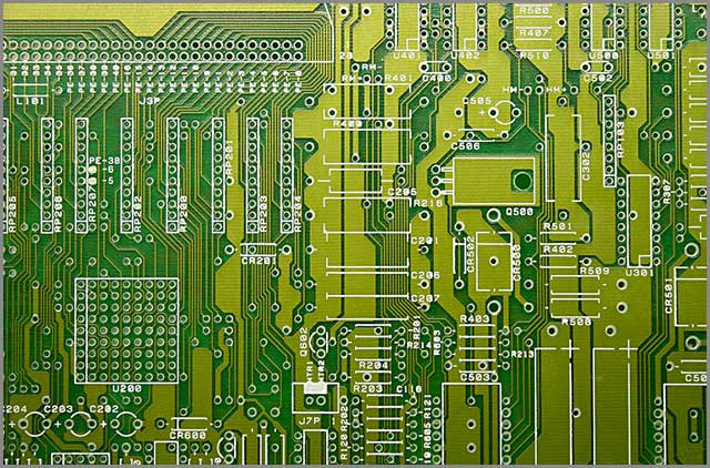
What are the Standards for Plated Thru-Hole Size?
Designers must consider several factors when evaluating and determining the final size of their PHTs.
The IPC has several standards and guidelines that every designer and manufacturer should consult.
Following these standards will make designs much more achievable in the real world.
The four steps to ensuring that you achieve the correct PTH size and lead size footprint are as follows:
- Approximate your design’s density
- Calculate the pad diameter
- Determine the plated-thru-hole diameter
- Approximate the maximum pad diameter
Thru-Hole Assembly Design Considerations
The first consideration applies to components. Generally, there are two types of thru-hole components, which you can distinguish by the kind of lead they have.
You can find your thru-hole component with either an axial or radial lead. You must consider the type of thru-hole component you’ll use for the assembly process.
Another factor to consider is the drill hole size. Manufacturers must drill or bore these holes about the aspect ratio of the PCB.
Finally, designers and manufacturers must consider the solder joint quality.
Applications of Thru-Hole Technology
Thru-hole PCBs and components are more suitable for harsh environments than SMT. As such, thru-hole technology is employed in industrial applications and aerospace and military solutions.
Thru-Hole PCB Manufacturers
When trying to bring your design to reality, it is important to select a reputable PCB manufacturer. WellPCB is one such manufacturer.
Whether your design requires a castellated hole or plated thru-hole, WellPCB will fabricate it according to your needs.
WellPCB offers excellent customer, high-quality assurance, robust quality control systems, and excellent return and refund services. Contact WellPCB and get an online quote today.
Conclusion
The current state of things is that, even though the two designs seem like constant completion, they are both widely used in the manufacture of electronics.
When it comes to repair and soldering of the Through-Hole boards, as discussed earlier, a lot of precision should be in place to ensure that the pins of the leads firmly fit and that you have a tight grasp of the components to be soldered.
This ultimately leads to your desire as an electronic enthusiast or what electronics you handle.