
Contents
1. LM386– When We use Headphones With our Audio Device Like Mobile
Laptop, FM, etc. The facility is adequate for the traditional users; however, not adequate for loud music listeners, or generally, we tend to get low sound from some devices. Thus to deal with this problem, we’ve created this handy hobby gadget, specifically phone electronic equipment. This circuit can be used as an amplifier to amplify the Subwoofer output and might be steam-powered by a transportable battery. Therefore the user will carry it anyplace. Check the entire details below.
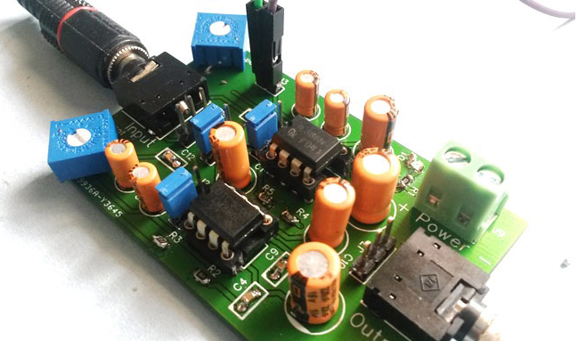
(Figure 1: Headphone audio amplifier circuit on PCB using wellpcb)
Requirements of components
- IC lm386 audio amplifier circuit (2)
- Fabricated PCB board (Wellpcb.com)
- Resistor 100k (2)
- The Resistor 22k (2)
- Resistor 1k
- The Resistor 10R (2)
- 3.5mm Audio Jack male/female (2)
- The Capacitor 100nF (4)
- The Capacitor 10uF (2)
- Capacitor 100uF (3)
- Capacitor 220uF (2)
- Bergsticks
- Power Supply
- LED

2. LM386–Circuit Diagram and Working Explanation
This phone electronic equipment Circuit is formed by mistreatment of lm386 audio amplifier circuit amplifier IC. This circuit is formed in such the simplest way that users cannot solely use it as phone electronic equipment. However, it can also drive a subwoofer speaker or traditional speaker (4 ohms) and might get a surprisingly loud sound through the speaker. To change it between these 2 modes, we’ve used 3 jumpers here.
Thus if the user desires to drive a subwoofer speaker, then he/she must assemble these jumpers, as we’ve explained below. Here we’ve used a 2 lm386 audio amplifier circuit, and the user will use three volts to nine volts to drive this circuit. We’ve got the jumpers configuration below in four cases to drive the phone or Speaker with Low or High gain. We’ve used Red color rectangular image to denote the position of the Blue jumpers; follow the red image to assemble the jumpers:
a:
To use it to amplify the Headphone output, we will assemble the jumpers as shown in the below image; during this case, each lm386 audio amplifier circuit IC works severally for the left and right speakers with low gain. The user will set the degree for each of the speakers of headphones severally by mistreatment 2 given potentiometers.
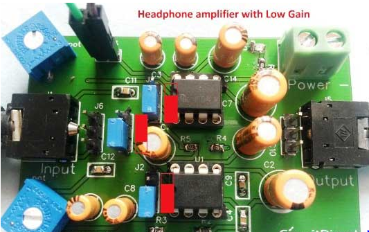
(Figure 2: Headphone amplifier with low gain)
b:
The second case is the same because the 1st one (Headphone Amplifier) solely tends to get high to gain this point. Once we assemble the jumpers shown in the below image, other than each lm386 audio amplifier circuit, ICs work severally for left and right speakers with a high gain at this point. The user will set the degree for each speaker of the phone severally by mistreatment of 2 given potentiometers.

(Figure 3: headphone amplifier with high gain)
c:
Within the third case, we will use a Subwoofer or Speaker (4 ohms/ 8-ohm speaker) to ever-changing the middle jumper position. Once we assemble the jumpers as shown in the below image, each IC adds a series with Low gain. The user will set the general volume by mistreatment 2 potentiometers. You’ll conjointly use headphones during this configuration. However, the degree ought to be below; otherwise, in high volume, phones could harm.
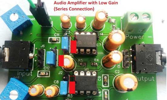
(Figure 4: Series connection audio amplifier having lower gain)
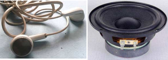
Giving audio input to the present Headphone/Audio electronic equipment Circuit, the user should use an AUX cable, which has three.5mm audio jack at each facet. One finish can be connected to the present circuit and one to the audio supply like mobile, laptop, etc.
 (Figure 5)
At the output finish of this circuit, you’ll either use straightforward Headphones/earphones or use Subwoofer or speaker. Keep in mind to tack together the jumpers, consequently as represented at the top.
The complete circuit diagram is shown below:
(Figure 7 Circuit diagram)
PCB design using wellpcb
They recently launched their part-sourcing service wherever
They need an outsized stock of electronic parts, and users will order their needed parts besides the PCB order.
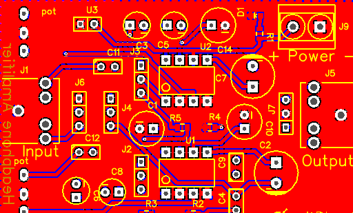
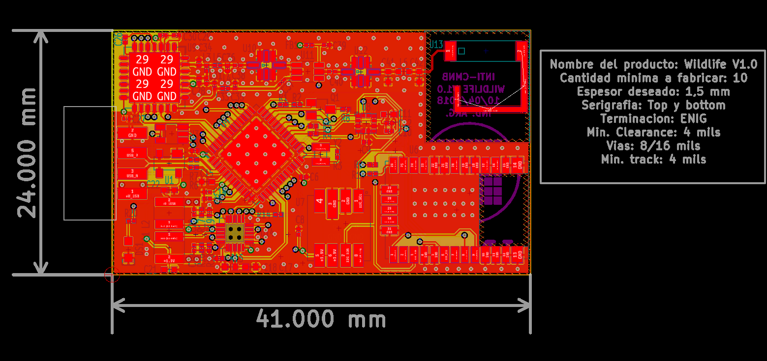
(Figure 8 Top layer PCB layout)

(Figure 9 Photo view of www.wellpcb.com can fabricate commonly used PCBs and custom PCBs. In addition to producing a PCB from an online platform with personal specifications, wellpcb audio amplifier)
3. LM386–Calculating and ordering samples online
After finishing the look of the PCB, you’ll be able to click and order it online. After that, you can try the prototype facility provided by the company. Here you’ll be able to read your PCB in Gerber Viewer or transfer Gerber files of your PCB. You’ll also be able to choose the quantity of PCBs you would like to order, what percentage of copper layers you wish, the PCB thickness, copper weight, etc. Finally, you can get an instant quote by using the link below:
Below is the PCB got from wellpcb.com:
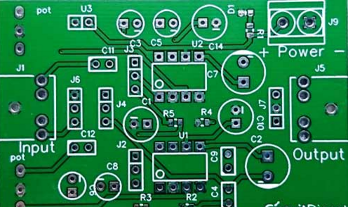
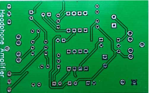
(Figure 10 PCB received from wellpcb.com)
Below are the images after the soldering of the components on the PCB:
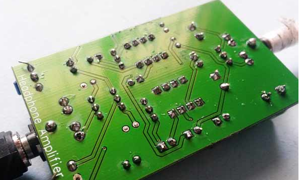
(Figure 11: Audio Amplifier Board Ready)


