
OrCAD is one of the most popular and premium design software offering circuit simulations and PCB design solutions. However, this document introduces you to OrCAD as the software used in designing DC circuits. It comprises three typical applications.
First, there is a Capture that is used to draw a course on the screen. Capture offers a lot of flexibility when compared with standard paper and pencil drawing. Secondly, PSpice works by simulating the captured circuit, and lastly, the PCB Editor. PCB Editor finds its use in the design of PCBs.
This handout explains how to use OrCAD to design DC circuits from the initial step to the end. Still, this article reviews if there is any other alternative software that can do the job and the social evaluation of OrCAD. Also discussed will be how to study this software further and why WellPCB is the best DC circuit maker currently in business.
Contents
- 1 What is OrCAD?
- 2 Do You Want to Design DC Circuits With OrCAD? Learning Steps
- 2.1 Step 1: Open OrCAD Capture
- 2.2 Step 2: Select or click on “new design” located on the “file” menu
- 2.3 Step 3: Search a new part through pinpointing the “place” icon and choosing “part.”
- 2.4 Step 4: Click/select the place in the schematic section where you intend to place the part.
- 2.5 Step 5: Do part editing
- 2.6 Step 6: Connecting many electrical parts
- 2.7 Step 7: Junction creation
- 3 IsThere any Other Software That Can Help You Solve The Problem?
- 4 Social Evaluation of OrCAD
- 5 How to Further Study OrCAD Software
- 6 Do You Have any Questions?
- 7 summary
What is OrCAD?
Made by a software firm known as OrCAD Systems Corporation, OrCAD is a software component used mainly for electronic design automation. OrCAD software finds heavy use by most industries and individuals though electronic technicians and design rely on it the most. They use it to simulate mixed signals and the design of DC circuits, among others. The name of this software is a portmanteau that reflects the firm and the origin of the software: Oregon + CAD. Hundreds of thousands of design engineers –especially DC circuit engineers- across the globe rely on OrCAD daily to solve tough design challenges. If you are a DC circuit designer and require a tool that you can build on, it is time you took a look at OrCAD. Being an award-winning technology software, OrCAD offers powerful and useful functionality to meet even demanding DC circuit designs.
Do You Want to Design DC Circuits With OrCAD? Learning Steps
If you intend to develop a DC circuit with OrCAD, you need to follow several levels for your project to be a success. Luckily enough, the steps to follow are not as complicated as you may imagine or perceive them to be. Unlike other tutorials that might be long and hard to comprehend, the learning steps to designing DC circuits using OrCAD are simple. The following are the learning steps to follow if you intend to design DC circuits with OrCAD:
Step 1: Open OrCAD Capture
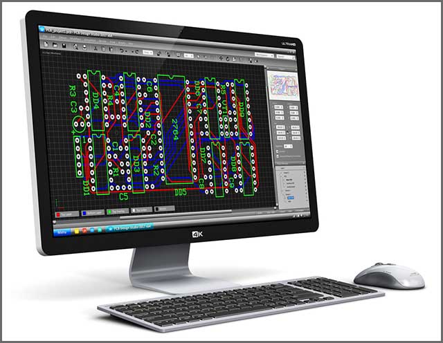
The first step to developing a DC circuit with OrCAD is by getting access to OrCAD Capture. As mentioned earlier, OrCAD Capture is a schematic design solution widely used by many circuit designers across the globe. Those dealing with DC circuits use it for creating and documenting their courses. OrCAD Capture is a powerful design solution that takes a product from concept to final production. Therefore, you need to open OrCAD Capture first.
After opening OrCAD Capture, now it’s time to move to the next step, where you have to click on the icon “new design.” You will easily find this feature under the “file” menu or icon tab. Of course, you are creating your new DC circuit, and therefore, you have to click on the “new design” icon. By clicking on this icon, you are now ready to proceed to the next step of creating a DC circuit.
Step 3: Search a new part through pinpointing the “place” icon and choosing “part.”
Searching for a new part is the third step of creating a DC circuit with OrCAD after completing phase 2 above. Here, all you have to do is to pinpoints the library to the location of the icon “part.” You will begin by typing or inputting the name of the part. You will have to do so in the box or place it under “Part.” At this point, there will be a display part under the “Part List,” and when you see this happen, click on it, and immediately, the window will shut/close.
Step 4: Click/select the place in the schematic section where you intend to place the part.
Have you completed step three above successfully without any challenges? If so, then it’s time to move to step 4. Step 4 is somewhat the easiest of all the steps involved in designing DC circuits using OrCAD. The only thing you have to do is select the location or place in the schematic section/page where you want the part placed. After you are done doing so, now it’s time to move to step 5.
Step 5: Do part editing
After completing step 4 above, you now have to edit the part. How do you go about doing this? It is a simple undertaking. You have to do this by first choosing or selecting it, then right-clicking, and finally, choosing the option you intend to edit. It is as simple as that. Are you done with this step? Move to step 6 below.
Step 6: Connecting many electrical parts
You are almost there. After completing phase 5 above, all you have to do is connect several electronic components.
You will have to do this by clicking on the ” Place wire” hat you will find from the drop-down menu or “Place.” Move to the last upon the completion of this step.
Step 7: Junction creation
Finally, you are there! Completing all of the above steps, all that’s left is a stage, and the DC circuit will be ready. Phase 7 involves junction creation between the wires that overlap each other. Creating a junction is achieved through clicking/selecting on the intersection. There you have it! Your DC circuit is now ready.

IsThere any Other Software That Can Help You Solve The Problem?
When it comes to the number of software that can aid engineers in designing DC circuits, there are plenty of them in the market to use. Even though OrCAD appears a popular choice, you will be surprised to find out that plenty of others are around. Although there are plenty of tools that engineers use, most of these tools are not soft on the pocket. Plenty of them is costly, a move that compels designers to look for cheaper options.
Nevertheless, other software platforms that can do the job, just like OrCAD, are there. Some of them include:
- KiCad EDA
- Circuit Maker
- Open Circuit Design Software
- nagaEDA
- Open Space
- ADC
- Simulate
- QSapacNG
- SuperSim
All the above and many others are alternatives that play precisely or almost the same role as OrCAD software in designing DC circuits.


Social Evaluation of OrCAD
While there are plenty of other software platforms used in designing DC circuits, OrCAD appears to tower them all. In short, one of the most popular ones used by hundreds of thousands of DC circuit designers across the globe is OrCAD. Due to OrCAD’s long-standing success, especially in designing DC circuits. OrCAD limits the additional complications that are brought about by unfamiliar or unproven technologies. OrCAD has positive ratings as one of the best and most reliable DC circuit software platforms to use. Unlike other platforms, OrCAD is feature-rich and a scalable platform that solves any DC design challenges fast.
How to Further Study OrCAD Software
Do you intend to learn more about OrCAD DC design software? If so, there are numerous ways of learning more about this popular software. For instance, an OrCAD Academic Program is fully committed to offering everything that educators, students, and researchers need to know. This program has a complete suite of analysis and design tools on teaching, learning, and coming up with electronic hardware.
Additionally, there is also free to download OrCAD software to students in addition to recommended textbooks. An apt example of such a book is titled ‘Analog Design and Simulation using OrCAD Capture and Spice, done by Dennis Fitzpatrick. Also, you can find a free edition for students in addition to OrCAD Capture Training, where one stands a chance to learn more regarding OrCAD.
Do You Have any Questions?
We at WellPCB are the largest professional PCB and DC circuit manufacturers around. Have advanced DC circuit design capabilities and offer some of the most exclusive services designed to meet your needs. We have industry-tested professionals with years of experience in designing DC circuits using OrCAD. Using OrCAD, we understand that we can route your DC circuit faster and more accurately. Additionally, we can build libraries and collaborate on all design domains at all the design steps.

summary
If you are in the market for a company that guarantees you affordable DC circuit design prices and on-time shipment, WellPCB is the best. Contact us to find out how to begin solving your PCB and DC circuit needs at your earliest discretion. We also provide 24-hour live support and an efficient online ordering system.