Contents
- 1 Why is PCB Thermal Simulation Important?
- 2 Types of PCB Thermal Simulation Models
- 3 Steps to Performing an Effective Thermal Simulation
- 4 PCB Properties Relevant to Thermal Simulation
- 5 What Boundary Conditions Do You Need to Worry About?
- 6 Common PCB Heat Generators
- 7 The Best Thermal Simulation Tools and Software
- 8 Conclusion
Why is PCB Thermal Simulation Important?
Why should you adopt a PCB thermal simulation and analysis as a workflow? First, consider how temperature, particularly heat, impacts the PCB.
When an electric current passes through a circuit (or any conductor), it produces heat as it encounters resistance. This is known as the Joule effect (or Joule heating).
The more resistance an electric current encounters in a circuit, the more electrical energy is converted into thermal energy.
This, in most cases, isn’t something you want, unless you’re planning to use that thermal energy in applications such as toasters or heating blankets.
Nevertheless, in most cases, thermal energy is seen as a loss. All conductors have resistance of some sort (this includes PCBs).
The heating effect can increase the conductor’s innate resistance. In turn, this creates a compounding effect on the heat.
Ultimately, you want your PCB to work as efficiently as possible. This Induces the am this amount of energy lost as heat.
If you’re designing your PCB for complex, high-performance applications, you must ensure that you keep the PCB’s temperature in mind. This includes implementing the necessary components and design measures to reduce emissivity.
Thermal simulation and analysis software enable you to test these h, which measures without building a prototype first.
Moreover, you can identify any weaknesses in your implemented measures and tweak them accordingly.
For instance, if you’re unhappy with your PCB’s thermal profile, you can use the thermal consider to test what effect turning the components or adding a larger heatsink would have.
In the long run, this allows you to save costs and time and improve the reliability of your printed circuit boards.
Types of PCB Thermal Simulation Models
Since your customers will use your PCBs under various circumstances, PCB simulation software must accommodate this. There are two main states or models for thermal simulation software:
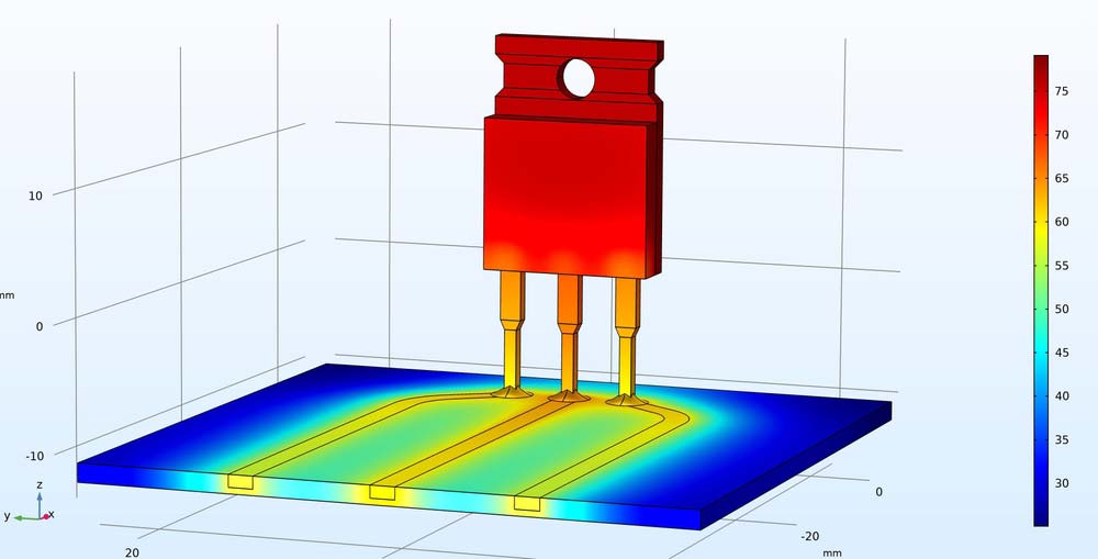
- Steady State: Tests the PCB under static, unchanging conditions. Essentially, designers use this method to assess the PCB’s ability to dissipate heat under normal operational circumstances. Technicians use this method early in the design phase.
- Transient Thermal Simulation: A more dynamic approach to thermal simulation. It assesses how the board will react to power cycling (being switched on and off) over a set period. This method allows designers and technicians to employ a more nuanced time-based approach to testing. It enables you to record the peak temperature of your PCBs during operation. Moreover, it also allows you to predict the PCB’s reliability and stability based on its thermal performance.
You should not worry about just the PCB and its substrate; PCB components have safe operating temperature ranges that must be maintained.

Modern Electronics Factory Supervisor using Design Software
Steps to Performing an Effective Thermal Simulation
The steps to a typical thermal simulation and evaluation workflow resemble the following:
- Construct the PCB Model: This entails setting up your PCB’s design within the simulation software. The details required in this step include the PCB’s dimensions, weight, layers, finishes, shape, and the components’ size (footprint).
- Defining the material properties of the model: This step requires you to input more detailed information about the PCB, including the material used in the substrate, the solder mask, etc. These details all factor into the thermal profile of the PCB.
- Identify and input figures for potential heat sources: Many of your PCB’s components will be conductors or resistors (or a mixture of the two). Consequently, some will have a higher resistance and thus generate more heat than others. In this step, you must input the values or properties of your components. This includes the luminous intensity of your LEDs, the conductivity and resistance of your IC packages, etc.
- Set thermal bounPCB’s thermal profile PCB won’t be operating in isolation, you must consider external thermal conditions. This includes airflow, ambient (room) temperature, and materials the PCB will contact.
- Apply the airflow: The simulation software will separate and encapsulate the PCB model into different parts (nodes). This will make identifying points of interest (heat spots) easier during the simulation.
- Execute the simulation: Determine the thermal profile of your PCB, analyze the results and refine the PCB’s design (if needed). Repeat the workflow until you’re satisfied with your PCB’s thermal performance.
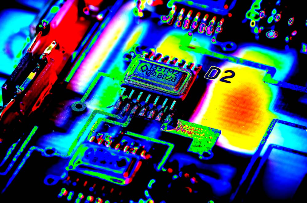
Part Printed Circuit Board Pseudo Infrared
PCB Properties Relevant to Thermal Simulation
The first step in most thermal simulation workflows is constructing or defining a PCB model. We mentioned just a few properties your PCB model will require. This section will provide you with a more complete list:
- Board assembly type (single side, multi-board, etc)
- Compound refine that
- Fiducials
- Resin content
- Laminate thickness
- Heatsinks
- Layer structures
- PCB dimensions/size
- Shape of the PCB
- Legends and silks
- Solder mask
- Resin content
- The total copper in the board (weight), including buried copper planes
- Thermal pads
- Traces
- Vias or holes
The above factors and properties will ultimately impact the PCB’s thermal profile. Of course, not all of them will apply to your PCB’s design.
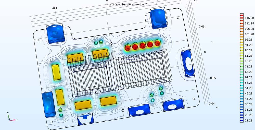
Computer 3d Modeling Temperature Distribution

What Boundary Conditions Do You Need to Worry About?
Setting boundary conditions is another step we covered in the PCB thermal simulation workflow section. Again, we only mentioned a few examples. A good PCB simulation and analysis tool should allow you to set the following boundary conditions:
- Modes of heat transfer (conduction, radiation, and convection)
- Ambient temperature
- Surrounding and adjacent objects
- Airflow-flow (from vents, fans, etc.)
- PCB mounting surfaces
- External heat sources
- Other environmental airflow (including pressure and humidity)
- Simulation state/model
- Thermal Interface Materials (TIMs)
Common PCB Heat Generators
When setting the values in your PCB thermal simulation and analysis software, you must pay special care to the properties of the following components:
- Connectors
- Integrated Circuits (IC)
- Regulators
- Resistors
- Transistors
- Optoelectronics
- Inductors
In addition to the above components, other common heat generators and sources include test points, large components, and high-density areas.
The Best Thermal Simulation Tools and Software
Through this guide, you should know what the perfect thermal simulation and analysis software should look like. To aid you along your journey, we’ve included some of the best options on the market:
- Siemens PADS Thermal Analysis: A comprehensive, general-purpose PCB design platform that caters to every aspect of PCB fabrication, including research, PCB analysis, and supply-chain insights.
- ANSYS Icepak: A fully featured thermal simulation and analysis tool for electronics – including circuit boards. Professionals favor it for its CAD-centric design, its Computational Fluid Dynamics (CFD) solver, and its use of multiphysics user interfaces.
- Autodesk CFD: A Computational Fluid Dynamics (CFD) software designed to simulate the thermal dissipation patterns of machinery and electronics components. Ultimately, its usages and applications aren’t limited to PCBs. It’s a CFD tool to test a litany of different systems.
- Cadence Celsius: A comprehensive electrothermal co-simulation solution. It features both transient and steady-state analysis. Moreover, the software allows you to import and analyze complex PCB designs with no input simplification. This allows you to quickly scaffold your models and perform thermal assessments as quickly as possible.
- Altium Designer: Another feature-rich PCB design software with a built-in thermal analyzer that allows you to simulate temperatures and thermal dissipation.
- COMSOL Multiphysics: General-purpose engineering simulation and analysis software. Despite its name, it is not limited to multiphysics modeling. It is also capable of single-physics modeling and coupling between the modeling types.
Conclusion
The above text provides a comprehensive guide on PCB thermal simulation software.
It covers the various steps in the typical thermal simulation workflow and the properties and factors to consider when using thermal simulation software.
We’ve also listed the best PCB thermal simulation and analysis tools.
Thermal simulation software can help you gain early insights into your PCB’s thermal performance and ensure that your designs are reliable and stable.
In addition to employing PCB thermal simulation software early in the design phase, you should also carefully consider the PCB manufacturer who will execute your design.
They have the most important role to play in your PCB’s success.


