Contents
- 1 PCB Temperature Briefly
- 2 Causes of High PCB Temperature
- 3 PCB Temperature Transfer Channels
- 4 PCB Temperature Tolerance
- 5 How to Measure PCB Temperature
- 6 Results Caused By Excessive PCB Temperature
- 7 Choosing the Right PCB Materials
- 8 Methods of Reducing PCB Temperature
- 9 What Temperature Should You Solder?
- 10 Why Should You Monitor PCB Temperature?
- 11 How Much Temperature is Good for a PCB?
- 12 Summary
PCB Temperature Briefly
PCBs are typically exposed to different heat levels during regular operation.
PCB temperature defines the degrees of heat the PCB can withstand during regular operation and storage.
PCB temperature is standard, medium, or high temperature.
The PCB’s material determines its temperature.
Aluminum has one of the highest PCB temperatures, making it useful in heavy industrial use.
Need professional PCB manufacturing services?
Our team has extensive experience and can provide a one-stop solution from design to production.
Click here: manufacturing PCBs
Causes of High PCB Temperature
The first step in micromanaging anything is to detect the source of the micromanagement needed.
PCB temperature is no exception. Since PCBs use heat to function, it is first necessary to determine the cause of the PCB’s high temperature.
High PCB temperature can lead to performance issues. When currents are too strong throughout a PCB, temperatures will rise.
There are three telltale signs of this anomaly.
Component dissipation
It is the first sign that temperatures in a PCB are rising too high.
One thing to remember here is that heat generated by a component is directly proportional to the load current that flows through the said component.
In this particular case, component dissipation occurs when one component of the PCB is not generating the kind of power it usually generates.
It causes other features to create more energy than usual to balance out the dissipating component.
If the current that travels through a resistor is inconsistent, the capacitor and other major circuit board components will carry a more significant charge than usual to compensate.
Through Hole
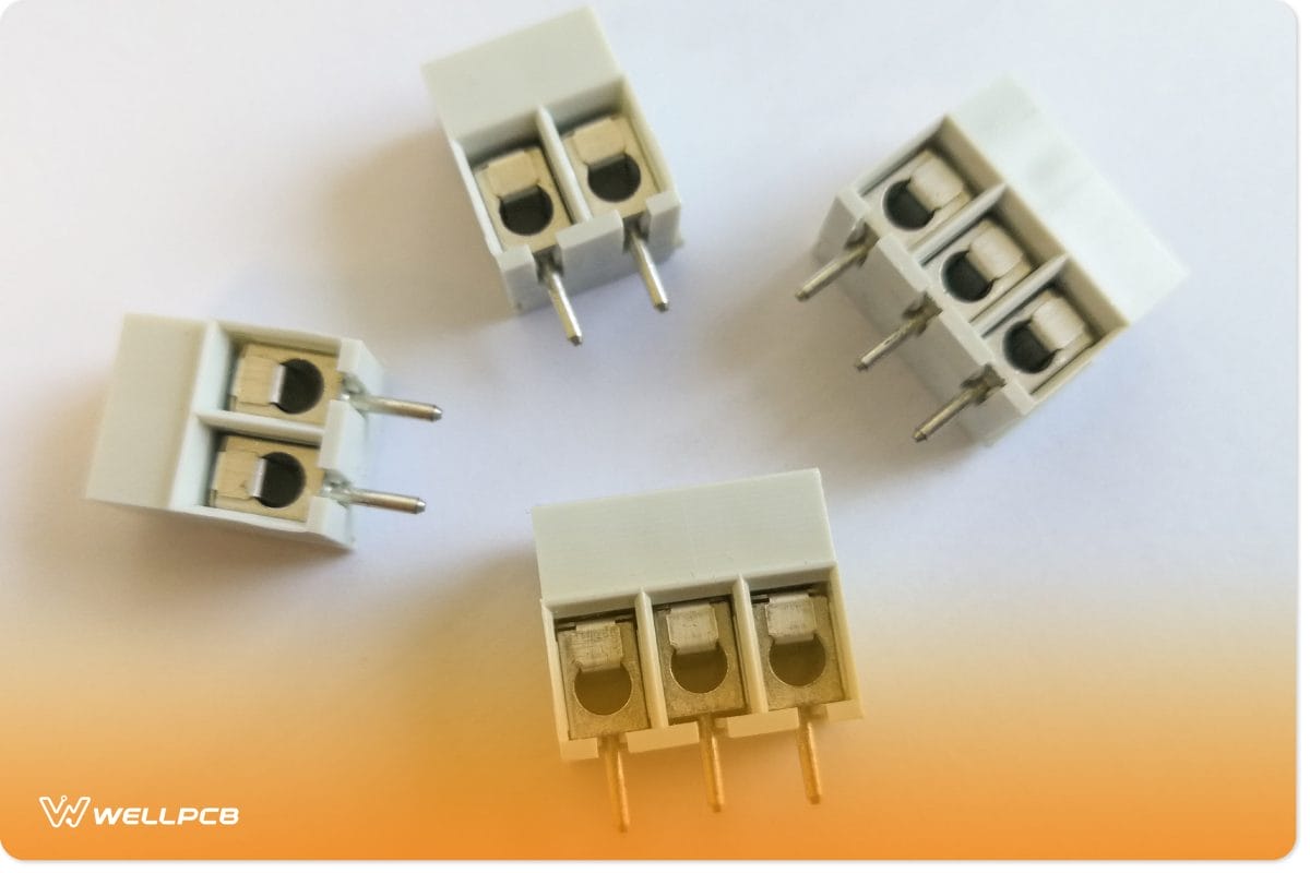
One of the most common things that provides power to a component is the heat sink, which is also known as a through-hole component.
These components generate heat by dissipating heat in the air. The heat sink makes this possible, and one way you can micromanage PCB temperatures here is to see if the heat sink is soldered correctly.
If another component on the PCB interferes with through-holes or heat sinks, the other features will work overtime to generate more heat than necessary.
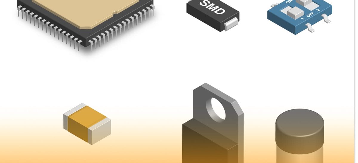
SMD components
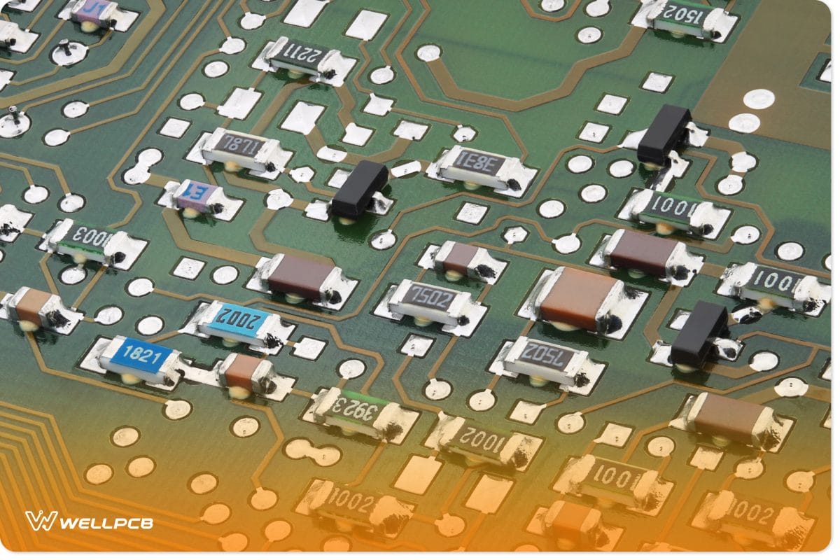
SMD stands for “surface-mount device.” It is connected to a PCB like a through-hole component and allows currents to travel smoother between the through-hole and heat sink components.
One of the most common issues with maintaining PCB temperatures is the position of the through-hole components on the PCB relative to the SMD components.
If they are too far away, the power might take too long to travel to and from these components.
It can result in the parts staying cool for too long, which will cause other members to overheat.
If they are too close to each other, the temperature will be unusually high.
A lot of this information comes from WellPCB, an organization that specializes in exploring new ways to micromanage PCB temperatures.
PCB Temperature Transfer Channels
A common thing about temperatures is that they are never static. Temperatures generally never stay the same. It is aware of this, as well as multiple channels of PCB temperature transmission.
Temperature is affected in many ways, and one way to micromanage the general temperature in your PCB and its components is to know not only about these channels but also what parts of the PCB utilize which channel.
Radiation
When people refer to thermal energy as electromagnetic waves, they are talking about radiation.
Radiating heat is usually generated passively, meaning that you cannot directly lower or increase the temperature by radiation.
Radiant heat has an almost negligible effect on PCB temperature.
At the same time, it is also the channel that you should probably worry about the most. This is because PCB temperatures are also affected by thermal energy.
When it comes to temperature, nothing is truly negligible. Think of what would happen if an airplane were to move just one degree off course.
If this happens, it will land in a different location than planned, no matter how short the distance could be.
PCB temperatures operate the same way. If a PCB needs to be at a temperature of 30 degrees Celsius to function optimally but stays at 32 degrees for a very long time, the results will not be desirable.
While there is no way to micromanage radiating heat directly, it is possible to micromanage radiating heat indirectly.
Being in an environment with consistent temperature when building and manufacturing PCBs is one way to do this.
Convection
Convection takes place when heat is transferred to fluids or air. Unlike radiation, convection is completely direct and has a powerful effect on overall PCB temperature.
The most famous example of convection is when cooking something. After all, nearly all ovens are convection ovens.
The heat from the oven is transferred to the air, which allows it to heat things.
“Cooking” also occurs when it comes to PCB materials. Just like it is essential to know your temperatures when preparing food in a kitchen, it is also necessary to know your temperatures when heating PCB materials.
Conduction
The most direct form of temperature transfer channel is conduction. In conduction, heat is transferred between a heat source and a heat sink.
The most potent example of this is when lightning strikes something metallic or fluid. In these examples, the heat source is lightning, and the heat sink is liquid or metallic.
Knowing what components of your PCB function as heat sources and which parts of the PCB function as heat sinks is an excellent way to determine when it is a good idea to decide what kinds of current components can withstand.
PCB Temperature Tolerance
PCB manufacturers also have trouble with overheating components in PCBs because they have not taken the time to learn what kinds of temperatures the material can withstand.
Every manufacturer should know this and make a list. Keeping a list on hand displaying how hot each material can get is very useful and, in many cases, necessary.
For example, the PCB panels contain a material called FR-4, which can withstand temperatures up to 90 to 110 degrees Celsius.
Therefore, when preparing a PCB with FR-4 materials, you should be aware of any currents that involve this material that could exceed 110 degrees Celsius.
Knowing what kinds of temperatures the panels of the PCBs you plan to manufacture is one of the most critical aspects of micromanaging the temperature of a PCB, but also one of the most overlooked.
How to Measure PCB Temperature
It is essential to understand what temperatures your PCB panel materials can withstand and how heat is transferred among the PCB’s components.
Knowing these things will help you micromanage your overall PCB temperature. Another thing that is good to know is how to measure PCB temperature.
In this case, measuring does not mean checking the displayed environmental temperatures.
It instead refers to measuring how the temperature increases and decreases.
Knowing these processes is one of the most accurate methods of measuring overall PCB temperature.
There are a few things that you need to identify before measuring PCB temperature this way.
These are the primary heat source and the temperature sensor. It is how most of the heat is generated and where most currents take place.
The next step is to find the heat source’s GND pin. It is usually connected to the heat source’s substrate.
After doing this, you can measure PCB temperature by doing these three things:
Using a common ground plane between the temperature sensor and the heat source.
You are connecting the GND pins of all temperature sensors to the ground plane of the heat source.
You are keeping the temperature sensor and heat source reasonably close to each other on the PCB.
Doing this will allow you to accurately and consistently track the global temperature of the PCB and the primary heat source.
Results Caused By Excessive PCB Temperature
Knowing how to measure PCB temperatures accurately and adequately is one thing. But what happens when the components and materials of a PCB get too hot?
Excessive temperatures will destroy the integrity of the layer.
What happens when something gets unusually hot or cold? They expand and contract, respectively.
PCBs are no different. The layers of the PCB are sensitive to temperatures.
Excessive temperatures will warp any PCB layer’s length, width, and thickness if they are not micromanaged.
Going back to the example of convection in Chapter 2, this is similar to leaving food in the microwave for too long, causing the food item inside to explode.
A similar thing happens to PCB layers if they are overheated.
Thermal energy expands most substances, altering them.
Substances expand when overheated, Altering their shape in some way.
Circuit materials are not exempt from this. High temperatures can and will change the shape of the transition lines in these circuit materials.
When this happens, it will change the dimensions of the circuit materials themselves.
It will result in straight losses, distortion, and frequency shifts in circuit materials.
Materials expand at different rates.
Materials in a PCB will not only expand when around high temperatures, but they will also expand at different rates.
The surface of a PCB is made up of either dielectric layers or conductive metal layers.
These layers expand to different limits at different speeds. These differences are not just separate from dielectric and conductive.
No dielectric or conductive layer is created equal.
One of the most common mistakes any PCB manufacturer can make is confusing these two layers.
Make sure to take the time to know which layer you are working with.
Board soldering requires different temperatures.
Welding and soldering is a necessary skill for anybody who wishes to produce, test, and manufacture PCBs.
Anyone in a PCB manufacturing firm who is not directly involved in welding and soldering needs to know what temperatures to work with.
Choosing the Right PCB Materials
Another way to micromanage and correctly set temperatures for PCBs is to choose the proper materials for the plates.
Choosing the wrong materials will make it much more complicated than it should be to micromanage these temperatures.
The most common material for a PCB plate is called FR-4. Anybody who is just starting in WellPCB. We will provide you with a one-stop service and high-quality products.
You can send us the documents you need to make and get a quote immediately! What are we waiting for?
We have ten years of PCB manufacturing, and those who want to minimize risks should choose this material.
A common thread about FR-4 materials is that they can resist temperatures well.
Two other materials are not as common as FR-4: polyimide and RF.
While these two do not resist temperatures and FR-4, they have other properties that FR-4 materials do not have.
This list will provide most of the information you’ll need regarding these materials regarding their specific temperature capacities.

Methods of Reducing PCB Temperature
Finally, it is time to explore ways to reduce PCB temperatures. These can be applied to any material of any PCB.
Heat sinks
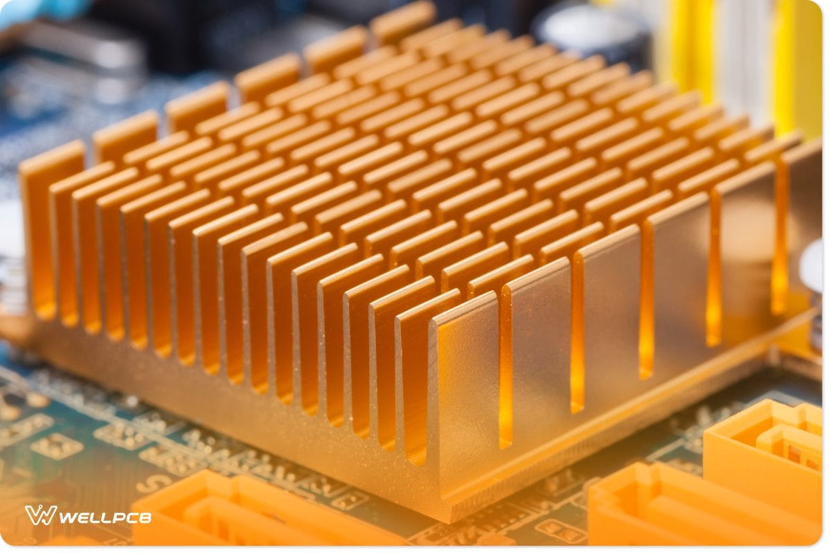
Parts, materials, and components of PCBs all generate heat. A proper heat sink will dissipate this heat, allowing for heat to be micromanaged.
Cooling fans
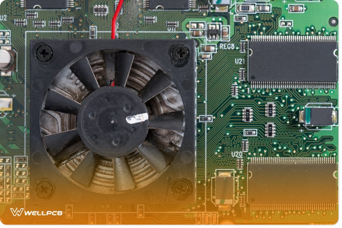
Nearly every electronic device contains a fan, but many do not understand what its purpose is.
Whether part of a fully completed electronic device or part of a WellPCB, we will provide you with one-stop service and high-quality products.
You can send us the documents you need to make and get a quote immediately! What are we waiting for?
We have ten years of PCB manufacturing devices; the purpose of a cooling fan is to allow hot air out of the device while letting cool air into it.
Thicker plates require more power to reach high temperatures.
Plate thickness is one of the more confusing issues that manufacturers face when dealing with PCB temperatures.
While thicker plates take more power to reach higher temperatures, the more comprehensive a dish is, the less it resists.
It can slow the temperature. This anomaly allows yet another method of controlling PCB temperatures.
Heat pipe integration considerations
What is the primary purpose of any given pipe? It is to organize the flow of any given substance.
It is also true when micromanaging PCB temperature, as liquids involved in PCB production can absorb heat, evaporate, and then condense back to liquid.
This kind of process allows you to continue working with whatever materials and components you need to work with while at the same time micromanaging the temperatures involved automatically.
What Temperature Should You Solder?
A good soldering outcome depends on the material you use. Otherwise, you risk incorrect placement or damaging the board and components.
For a lead-based solder, you must set your equipment to the lead’s melting point. Lead’s melting point is between 600 and 650 degrees Fahrenheit(316°- 343°C).
However, you can also use non-lead material to solder.
In this case, set your equipment starting at 650 degrees Fahrenheit to 700 degrees Fahrenheit(343°- 371°C).
Maintain these soldering heat limits to maintain the soldering tip’s lifespan.
Why Should You Monitor PCB Temperature?
Improper temperature management in PCB manufacturing or handling has a domino effect, ultimately resulting in total failure of the PCB.
Any problems caused by not monitoring PCB temperature spread to more parts of the board.
Monitoring PCB temperature is important for the following reasons.
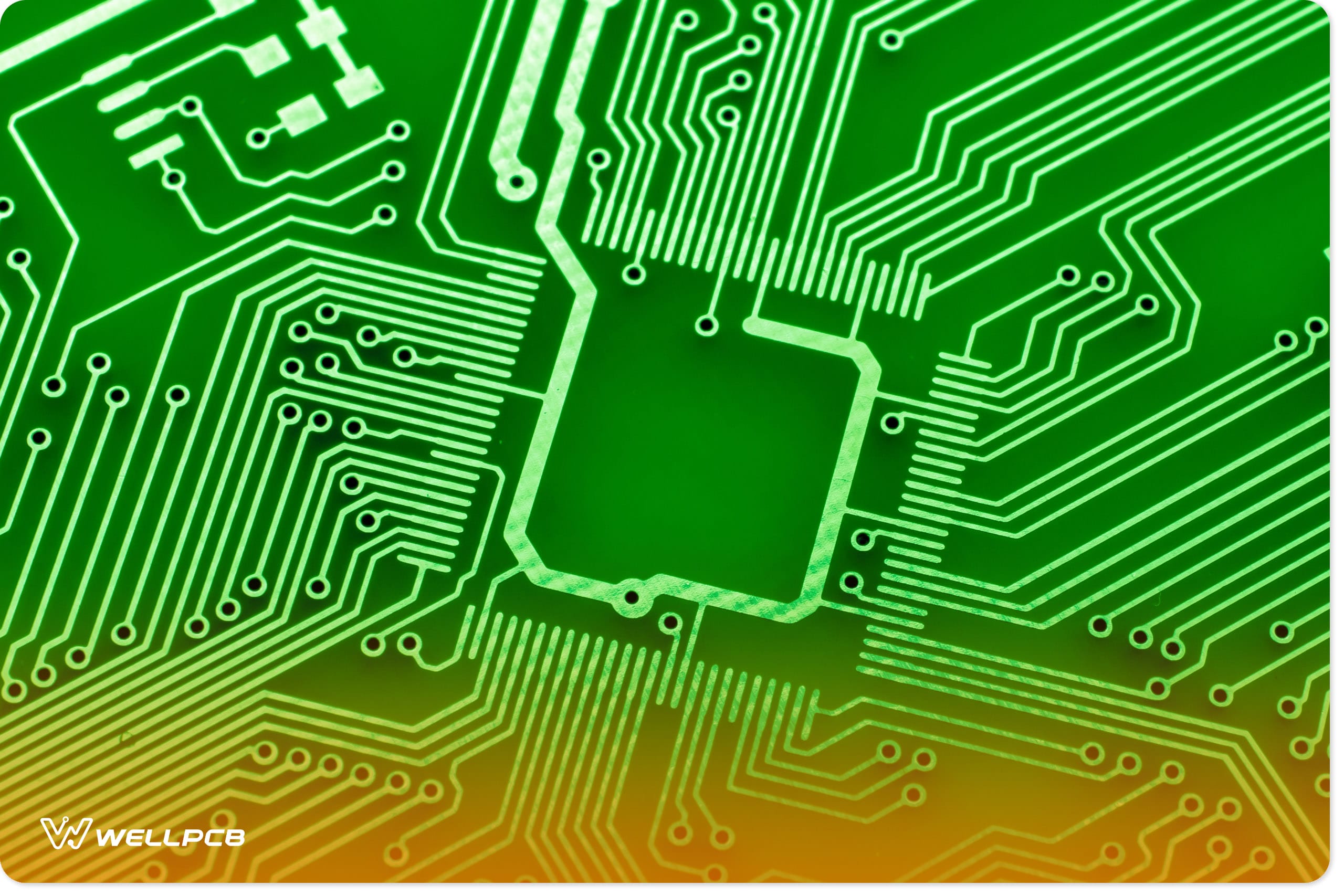
It Prevents Circuit Line Disruption
Circuit line disruptions are a common negative effect of overheating.
You risk expanding and changing the circuit line shape by applying too much heat. Further problems stemming from circuit line disruptions include:
- Changing conductor impedance value from 50 ohms
- Frequency shifts
- Damaged millimeter-wave and microwave circuits
Ultimately, you lose the entire PCB.
It Prevents Component Oxidation
Monitoring prevents overheating which erodes the laminate coating, exposing the PCB’s dialectic material.
Without the laminate coating, the material becomes susceptible to oxidation, which leads to rust. Rust leads to high dissipation and eventual loss of transmission lines.
Monitoring Prevents Unequal Material Expansion
PCBs have a debate and conductive metal layer, each with a different expansion rate.
Monitoring prevents overheating that would otherwise expose each layer to expansion and eventual separation.
The layers would pull apart, ruining the entire PCB.
Monitoring is Important in Maintaining the PCB Structure
PCB layers are precisely measured during the design phase.
Close observation prevents overheating that expands different layers and distorts the PCB’s different dimensions.
Dimension distortion renders the PCB uneven and unusable.
How Much Temperature is Good for a PCB?
A good temperature for a PCB ranges between 194 to 230 degrees Fahrenheit(90 to 110 degrees Celsius).
This temperature range is standard for FR-4 or glass epoxy laminate PCBs, which comprise most of the available PCBs.
However, some PCBs made for high heat tolerance with materials such as ARLON 85N and VT-90H can withstand temperatures up to 338 degrees Fahrenheit(170 degrees Celsius).
These PCBs are known as high-temperature PCBs, and they’re perfect for maximum glass transition.
What temperature will damage a PCB?
Standard PCBs that can withstand regular temperatures will retain their structural integrity at about 248 degrees Fahrenheit (120 degrees Celsius).
Yet, PCBs designed for high-heat operations can withstand about 338 degrees Fahrenheit(170 degrees Celsius).
Temperature damage on PCBs depends on the material. Materials such as aluminum can withstand temperatures as high as 1220 degrees Fahrenheit (600 degrees Celsius) before they melt.
What temperature should PCB be stored at?
You must store your PCBs in a monitored environment between 53 and 86°F.
Also, the environment must maintain humidity levels below 75-85% for the PCB to maintain its conductive state and avoid oxidation.
Limit the storage time to between 2 and 10 years in the monitored environment.
What is the temperature class of PCB?
PCB temperature class is a rating system that determines the maximum surface heat a PCB can take before it is a fire hazard during operation.
The rating, from T1 to T6, starts as low as 185 degrees Fahrenheit for T6 to as high as 842 degrees Fahrenheit for T1.
Check the protection and material of the PCB to know the temperature class of the PCB. Also, it’ll be on the product label.
Summary
If you possess an acute attention to detail and are well informed, it is not difficult to understand the causes and solutions surrounding PCB temperature.
Additional information can be found in WellPCB’s article archives as well.
There are many things to learn when it comes to micromanaging PCB temperatures, and the key to doing this is to be patient and consistent.
Mastering the art of managing PCB temperatures takes time, and guides like this are designed to save a lot of it.
WellPCB has been specializing in the correct PCB service provider. Thankfully, there have been various PCB manufacturing fields for some time.
We are committed to providing information for other PCB manufacturers and providing the best materials, components, and services for both.