
Contents
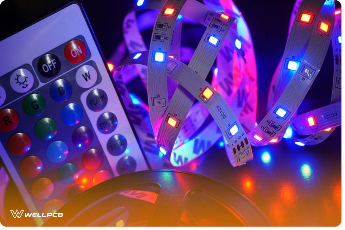
Types of RGB LED Controllers (Wireless)
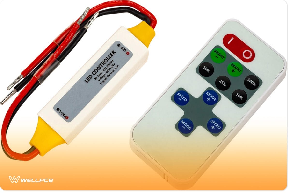
Controller for RGB LED with remote control.
There are two fundamental types of RGB LED controllers: wired and wireless.
For the wired strip controller, you can only use it when it’s close to the LED product or RGB strips. Hence, the most convenient option is the wireless controller.
That said, here are some wireless types of RGB LED controllers that are available:
Color Wheel Remote
This remote is ideal if you want more control over your 12v RGB LED strip. That is, the color wheel remote allows you to quickly and easily select the color of your RGB LEDs.
Basic Wireless RGB LED Controller
This controller gives room for customizing your RGB bright LED strips. It also allows you to pre-program the strip’s color change speed. Plus, you can adjust the brightness of the colors with this controller.
App Remote
With remotes like this, all you need is an ambient device like a tablet or smartphone (android device). And you’ll easily control the settings of your RGB LEDs. So, this is a more flexible option, considering that it offers you control over your lights to multiple people.
How Does an RGB LED Controller Work?
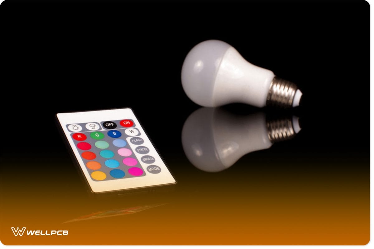
Remote control for LED theme light bulb
The primary function of the RGB LED controller is to make a particular color mix. And it achieves this by modifying the power on each of the three channels (R, G, and B).
For instance, if you want a purple hue, the controller will produce it by wounding up the red and blue channels. In the process, the controller will shut the green channel.
How Do You Make an RGB LED Controller Circuit?
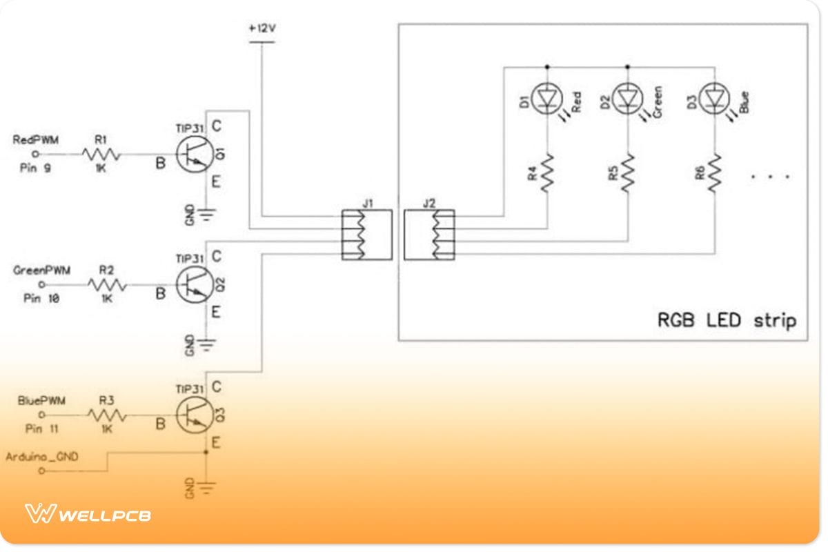
RGB LED controller circuit
The Design
This RGB LED controller circuit uses a PWM (Pulse Width Modulation). And it helps to produce color-changing effects. Also, the course regulates three outputs. Each of the outputs can work on the LED segment.
You’ll also find fully customizable sequences at the microcontroller that can fade, cycle, and strobe the color-rich lighting. Consequently, this helps create a huge palette with more than 15 million color options. That said, every output has 8-bits (resolution).
Hence, the circuit offers each color different intensities (over 256). So, you’ll get a complete rainbow combination when three colors mix.
Components Needed
- LED rainbow board
- Red, green, and blue PWM switch
- DC Power Jack P1 (1)
- 1N4002 D1 (1)
- 8-pin DIP Socket U2 (1)
- LED rainbow processor U2 (1)
- PCB mount push button switch S1 (1)
- STP36NF06 N-channel MOSFET D1, D2, and D3 (3)
- LM78L05 5-volt regulator TO-92 Case U1 (1)
- 1K ohm (brown-black-red-gold) R1, R2, R3, R4, R5, R6 (6)
- .1uF C2- optional (1)
- .1uF C3 (1)
- 33uF 50v electrolytic capacitor C1 (1)
Steps
Step 1
Get a clean surface to work. And set all your components aside for easy access.
Step 2
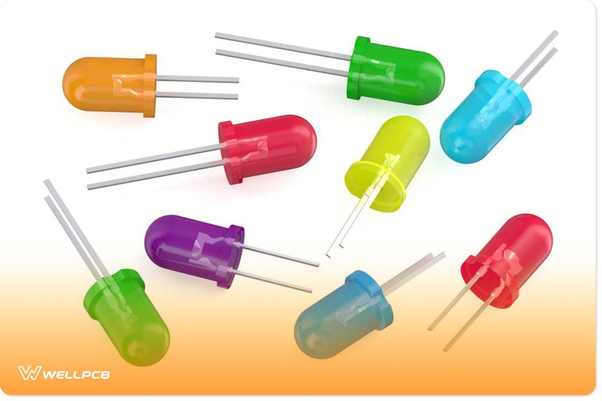
diodes
Place your diode (1N4002) on the silver bar on the diode. You can find the diode’s cathode on the silver rod of the component, and it should blend with the PCB’s silkscreen. So, your diode should face the component’s bottom. Then, solder the 1N4002.
Step 3
PCB
Typically, the LM73L05 has a half-circle on its flat side. Hence, this component should face the board’s bottom. With this, you can put the regulator at U1 and solder. That way, the setting will match the PCB’s silkscreen.
Step 4
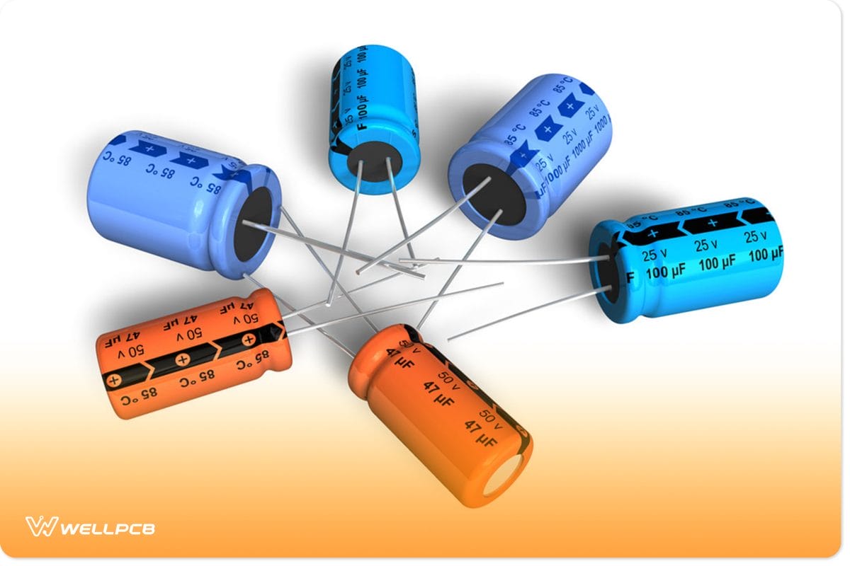
capacitors
Since the capacitor isn’t polarized, you can fix it either way. With this in mind, solder the C3.
Step 5
At this point, the 33uF electrolytic capacitor is next. But you have to pay attention to the markings on the component. Typically, you’ll see a minus sign on the negative lead—marked outside. With this in mind, place only the negative information into the board’s hole and the positive sign out. Then, fix the C1 and secure it firmly.
Step 6
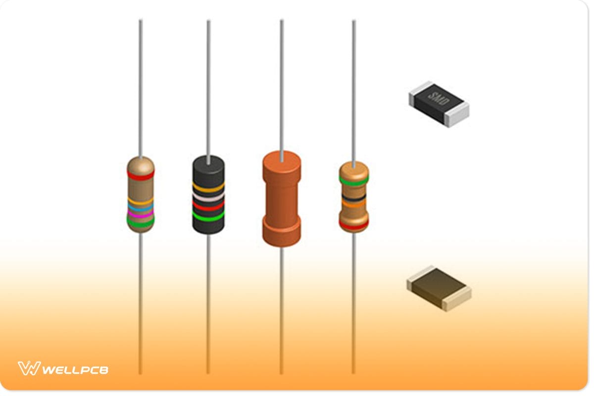
resistors
Next, you can move to the resistors (R1, R2, R3) with brown-black-red-gold color. Interestingly, they aren’t sensitive to polarity.
So, you can fix the resistors in any direction. But your resistors have to stand on one end. And you can get that by bending the leads and soldering them in place.
Step 7
At S1, fix the push button. No doubt, the switch doesn’t have polarity, but you can fit the button on the board in one direction. You can try different ways to see the best fit since the switch is more comprehensive than tall. When you place the button correctly, it will enter the board gently. Afterward, solder the switch in S1.
Step 8
Place the 8-pin IC socket in U2. The socket is responsible for clasping the PIC Processor LED Rainbow controller. After proper positioning, solder the socket U2.
Step 9
Next, fix the three STP36NF06 at Q1, Q2, and Q3. But, it’s crucial to handle the STP36NF06 carefully because it’s sensitive to static electricity. Also, a metal panel on the MOSFETs’ back is a heat sink. So, it would help if you paired the heat sink with the PCB’s silkscreen (solid white pattern). Once everything aligns, solder Q1, Q2, and Q3.
Step 10
Proceed to place the optional jack at P1. With the jack, you can activate the LED Rainbow PCB. Regardless of the available power jack, it can fit into the board’s hole pattern. With this, you can place the power jack at P1.
Step 11
Fix the LED Rainbow controller at U2’s socket. While you’re doing it, ensure that the controller’s Pin 1 faces up when you put it in the socket. You can spot Pin 1 in the corner of the chip with a slight indentation. Also, it’s vital to note that you may cause damage if you place the processor backward and add power. With this, you can fix your LED Rainbow controller at U2.
Step 12
Now that your LED Rainbow controller system is complete connect the RGB to your board. Alternatively, you can link the LEDs (Red, Blue, and Green) individually to your board. Then, test the setup.
Important Things to Note
LED strip in purple colors and a control panel for switching colors
- Ensure that you do your soldering on the board’s back.
- Do your soldering carefully because it determines if your project will work or not.
- Assemble your components on the board one at a time. You can start with the smallest parts closest to the board. That way, you’ll confirm components that are working correctly.
- If you don’t have enough experience with assembly, opt for a fully assembled and tested board.
Rounding Up
An RGB LED system makes it possible for you to have a variety of colored lighting. But when it comes to controlling the lights, you need the RGB LED controller circuit. The controller circuit works by modifying the power of the three channels: Red, Blue, and Green.
No doubt, it may be expensive to get a controller circuit. However, you can build a more affordable option with industry-standard parts. All you need to do is follow the steps in this article.
That said, are you ready to jump on this lighting project? Or do you need help with setting up? Please feel free to reach us.


