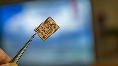
Digital circuits or digital electronics are electronics that use digital signals. They’re different from analog circuits in that analog circuits operate on analog signals whose operation is much more subject to signal attenuation, manufacturing tolerance, and noise typically, designers use large assemblies of logic gates on integrated circuits to make digital circuits.
In this friendly guide, we let you know everything about digital circuits. Read on to learn more.
Contents
A Brief History of Digital Circuits
In 1705, Gottfried Wilhelm Leibniz refined the binary number system. Leibniz established that by using the binary system, it was possible to join the principles of arithmetic and logic. In the mid-19th century, George Boole conceived digital philosophy as we know it today. Later, in 1886, Charles Sanders Peirce explained how scientists could carry out logical operations by switching electrical switching circuits. Then, instead of relays for logic operations, designers started to use vacuum tubes.
With the development of digital computers after World War II, numeric calculation replaced analog. Soon, purely electronic circuit elements took over from their mechanical and electromechanical counterparts.
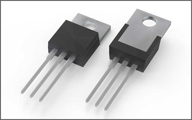
In 1959, Mohamed Atalla and Dawon Kahng invented the MOSFET transistor, which dramatically revolutionized the electronics industry. From the late 20th century, the MOSFET transistor played an integral role in the building of digital circuits. Currently, it’s the most popular semiconductor device globally.
Initially, each integrated circuit chip had only a few transistors. As technology advanced, it became possible to place millions of MOSFET transistors in a single chip. Today, designers can place billions of MOSFET transistors in a single chip. It’s evidence of how far digital circuits have progressed since their early days.
2. Properties of Digital Circuits
One of the biggest reasons digital circuits are highly accessible, as we mentioned earlier, is that it’s easy to represent them digitally without noise degrading them. For example, as long as the sound picked up during transmission is not sufficient to prevent the route from being identified, successive audio signals can be reconstructed in the order of 1 s and 0 s without any errors.
To obtain a more precise representation in a digital system, you can represent the signal using more binary digits. Of course, that requires more digital circuits, but since the same kind of hardware handles each number, the system is easily scalable. Things are different with an analog system that needs fundamental improvements in the noise characteristics and linearity to produce a new resolution.
Where you’re using computer-controlled digital systems, it’s possible to add many more functions using software revision. In other words, you don’t need any hardware changes. Moreover, you can introduce any improvements in your digital system outside the factory by merely updating the software.
Another property of digital circuits is that they allow more accessible storage of information. This is because digital systems are immune to interference and can store and retrieve data without degrading performance.
Many of the latest digital systems typically translate continuous analog systems to digital signals. This may cause quantization errors. To keep these errors are a minimum, make sure that the digital system can store adequate digital data to represent the signal to a desirable degree of fidelity.
3. Construction of Digital Circuits
Engineers use various ways to construct logic gates. We’ll investigate some of them below.
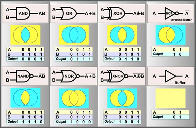
3.1 Construction Using Logic Gates
Manufacturers of digital circuits typically use small electronic circuits known as logic gates to create digital courses. With these logic gates, it’s possible to create combinational logic. Each logic gate acts on logic signals to perform a function of Boolean logic. Generally, designers use electronically controlled switches to create logic gates. Usually, these switches are transistors. Thermionic valves can also help to do the same job. The output from one logic gate can feed into other logic gates or control them.
3.2 Construction Using Lookup Tables
The second type of digital circuits features construction from lookup tables. Typically, lookup tables perform similar functions as digital circuits based on logic gates. A significant benefit of digital channels based on lookup tables is that designers can easily reprogram them without making any changes to the wiring. In other words, it’s easy to repair design errors without needing to change the arrangement of the wires. When dealing with small volume products, designers thus prefer programmable logic devices to other kinds of digital circuits. In designing these programmable logic devices, engineers typically use design automation software.
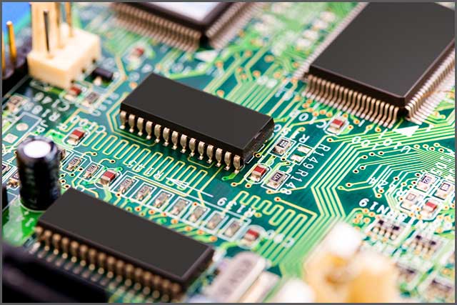
3.3 Integrated Circuits
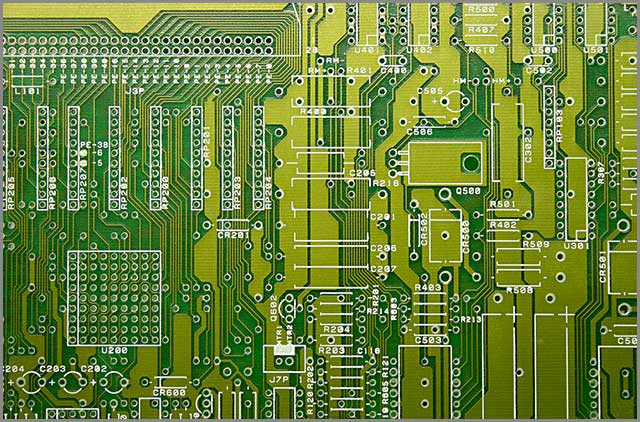
In constructing integrated circuits, engineers use multiple transistors on one silicon chip. This is the most affordable way to create a large volume of interconnected logic gates. Usually, designers interconnect integrated circuits on a printed circuit board (PCB), which is a board that holds various electrical components and connects them with copper traces.

4. Design of Digital Circuits
In designing digital circuits, engineers use various ways to reduce logic redundancy, hence keeping circuit complexity at a minimum. But why is it essential to keep circuit complexity low? Well, minimal complexity reduces component count and averts potential errors, which in turn keeps costs low. Some of the most common techniques of reducing logic redundancy include Boolean algebra, binary decision diagrams, the Quine–McCluskey algorithm, Karnaugh maps, and the heuristic computer method. Software engineers typically use heuristic computer methods to perform these operations.
4.1 Representation
Representation is an essential part when it comes to the design of digital circuits. The classical engineers represent digital circuits is using an equivalent set of logic gates where designers use a different shape to represent each logic symbol. Engineers can also construct an equivalent system of electronic switches to represent digital circuits. Representations usually have numeric file formats for automated analysis.
4.1.1 Combinational vs. Sequential
In choosing images, designers typically consider various types of digital systems. The two common groups of digital systems are combinational systems and sequential systems. Combinational systems present the same outputs for the same inputs. Sequential systems, on the other hand, are combinational systems that feedback some of the outputs as inputs.
There are two further subcategories of sequential systems: synchronous sequential systems that change state all at once and asynchronous sequential systems that change every time inputs change.
4.1.2 Computer Design
A computer is the most ordinary general-purpose register-transfer logic equipment. The machine is an automatic binary abacus. A micro-sequencer runs the control unit of the network, which is itself a micro-program. The vast majority of computers are synchronous, although there have also been asynchronous computers in the market.
4.2 Design Concerns in Digital Circuits
As engineers use analog components in digital electronic circuits, the analog nature of such components can interfere with the desired digital behavior. The design of digital channels thus needs to manage topics such as timing margins, noise, capacitance, and parasitic inductances.
4.3 Digital Circuit Design Tools
Through the years, engineers have designed sizeable logic machines that aim at minimizing costly engineering effort. Currently, there are computer programs known as electronic design automation tools (EDA) that exist for this purpose. For instance, there’s a manufacturability software that provides excellent assistance to designers of digital circuits.
4.4 Testing a Logic Circuit
The main reason engineers test a logic circuit if to verify whether the design meets the timing and functional specifications. It is crucial to examine each copy of the digital channel to ascertain that the manufacturing process has not introduced flaws.
5. Digital Circuit Design Considerations
The progression of the design of digital circuits has been slow but steady. We trace this journey by looking at the various logic families below.
5.1 Relays
The first design of digital channels featured relay logic. This design was reliable and inexpensive. However, it was slow, and there were occasional mechanical failures. There were typically ten fanouts that arced on the contacts.
5.2 Vacuums
Vacuum logic immediately followed relay logic. The main benefit of vacuums was that they were swift. However, vacuums generated a lot of heat, and the filaments would frequently burn out. The development of computer tubes in the 1950s was a significant improvement in voids as these computer tubes could run for hundreds of thousands of hours.
5.3 Resistor-Transistor Logic
This was the first semiconductor logic family. The resistor transistor logic was thousands of times more reliable than tubes. It used much less power and ran cooler. However, it’s fan-out was very low: 3 in total. Later the diode transistor logic boosted the fan-out to 7 and further reduced the power.
5.4 Transistor-Transistor Logic
A dramatic improvement over previous logics, the transistor-transistor logic had a fan-out of 10. Later, that fan-out improved to 20. This logic was also remarkably fast. The logic is still in use today in specific digital circuit designs.
5.5 Emitter Coupled Logic
The emitter-coupled model is incredibly fast. However, this logic uses a lot of power. High-performance computers with medium-scale components extensively use this logic.
5.6 CMOS Logic
CMOS logic is by far the most popular logic for integrated circuits today. The logic is fast, provides high circuit density and low-power per logic gate. Even large fast computers use this logic.
The Latest Developments in the Field of Digital Circuits
Researchers in the field of digital circuits have recently made significant progress. Below are some examples:
6.1 Use of Memristors
In 2009, for instance, researchers found out that memristors can help implement Boolean state storage. This provides a complete logic family that features small amounts of power and space with the use of simple CMOS processes.
6.2 The Discovery of RSFQ
Researchers have also discovered superconductivity. This discovery makes it possible for engineers to develop rapid single flux quantum (RSFQ) circuit technology that makes use of Josephson junctions rather than transistors. Engineers have most recently been attempting to construct purely optical computing systems that can process digital information using nonlinear visual elements.
Summary
Digital circuits are at the center of today’s digital electronics and computer processing. With their low susceptibility to noise and quality degradation, these circuits are far more preferable to analog circuits. And with engineers and researchers dedicating themselves to the progress of the field of digital channels, the design and performance of these devices will only get better.
Are you looking for digital circuits that will perfectly meet your unique needs? At WellPCB, we dedicate ourselves to delivering top quality digital circuit solutions to our customers all over the world. Visit our website today to learn more about our services.